
Some time ago we (Ipswich Makerspace) found a local business which had a laser cutter and was happy to do cutting for us. This was pretty handy for last years (2014) PiWars where we started with a stock platform which Keith redesigned and enhanced to create TractorBot 2014. Fast forward to a couple of months ago when we were going through the same process with TractorBot 2015 when disaster struck. The main board on the laser cutter went down and the repair cost was eye-watering. Being the true souls of repair, re-use, re-cycle we are (read desperate) we investigated fixing it ourselves. On balance we could probably have got it back up and running but the commercial risk was just too great for them. We were in a bind, right up to the moment someone said “We could get a cheap Chinese cutter!”. It must have been Phil that said it because shortly after he posted that a ‘mystery’ crate was on the way.
This is the story of Phil’s Laser Cutter Adventure told mostly in his own words. There was some initial amusement as we cast knowing engineering eyes over it, for example the aquarium pump ‘cooling system’. Or the clever ‘hole in the bottom’ ventilation. The software raised a few eyebrows too. But with a bit of effort, quite a bit of effort really, Phil was able to wrestle this cheap gadget into a hi-tech manufacturing tool. Let’s hope it lasts until we’ve cut all the bits for PiWars.
Laser Cutter Adventure – Part 1
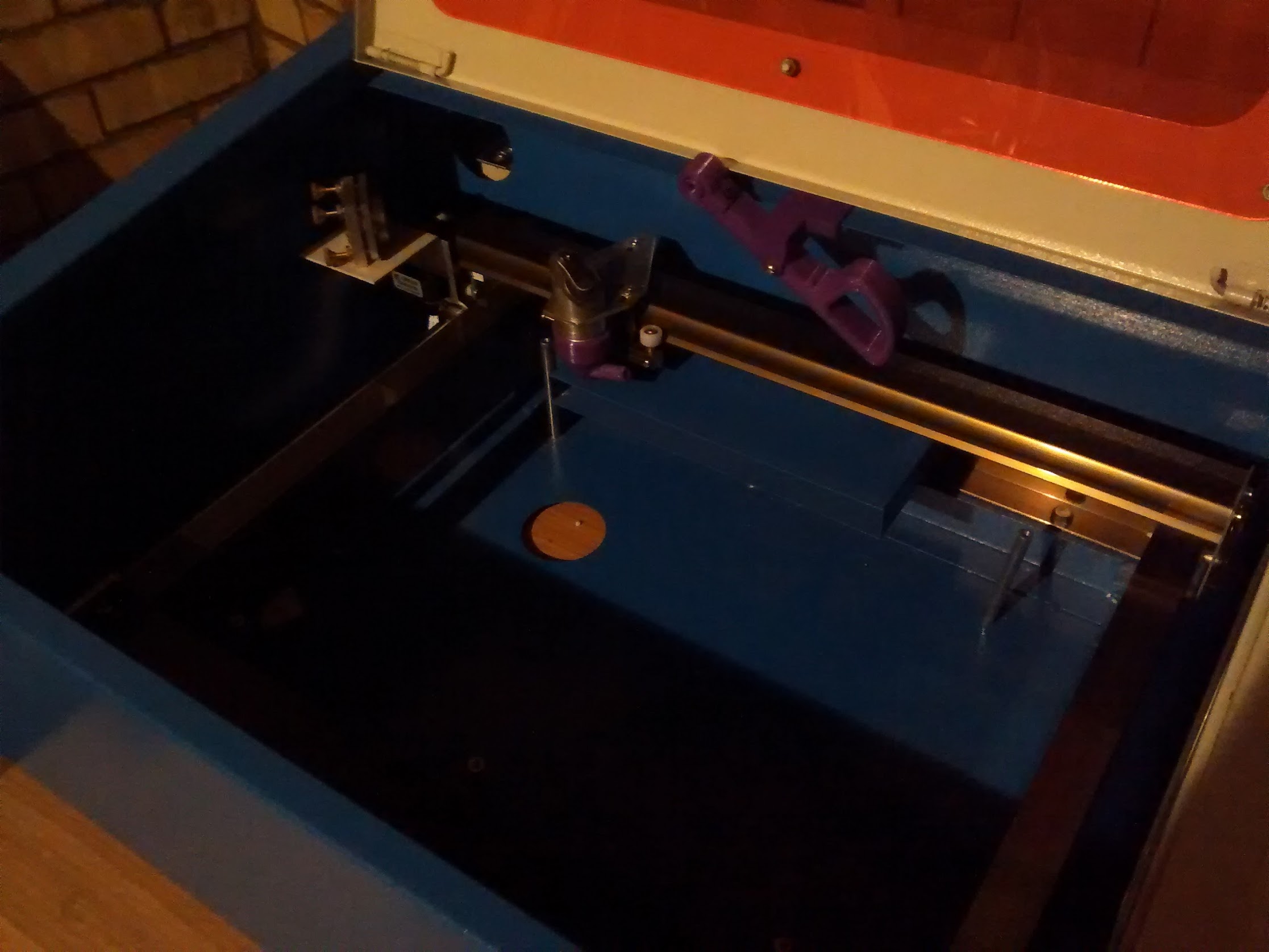 The cutter is now sited in the garage on an old table, which has some handy drawers in the front. The first job was removal of the current engraving frame (before and after images). Note the 3D printed laser pointer holder and air assist nozzle, not sure if I will use these yet as I have found some more on thingiverse.com which might prove better.
Also note the hole in the bottom of the case!!! (Visions of laser cutting the desk, ed.)
The air duct at the back could do with being trimmed down as well.
Laser Cutter Adventure – Part 2
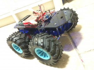
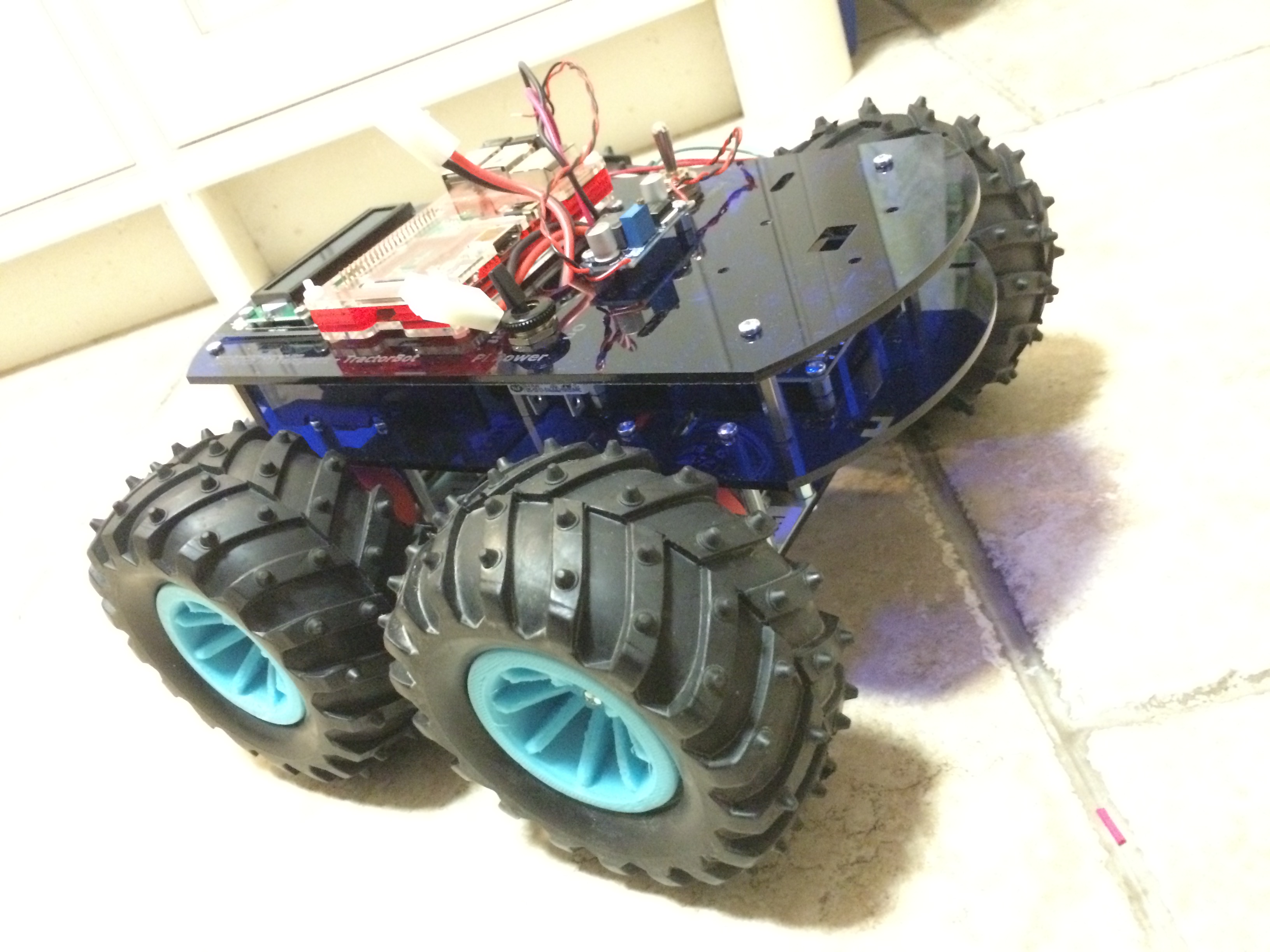
TractorBot 2014 base for comparison
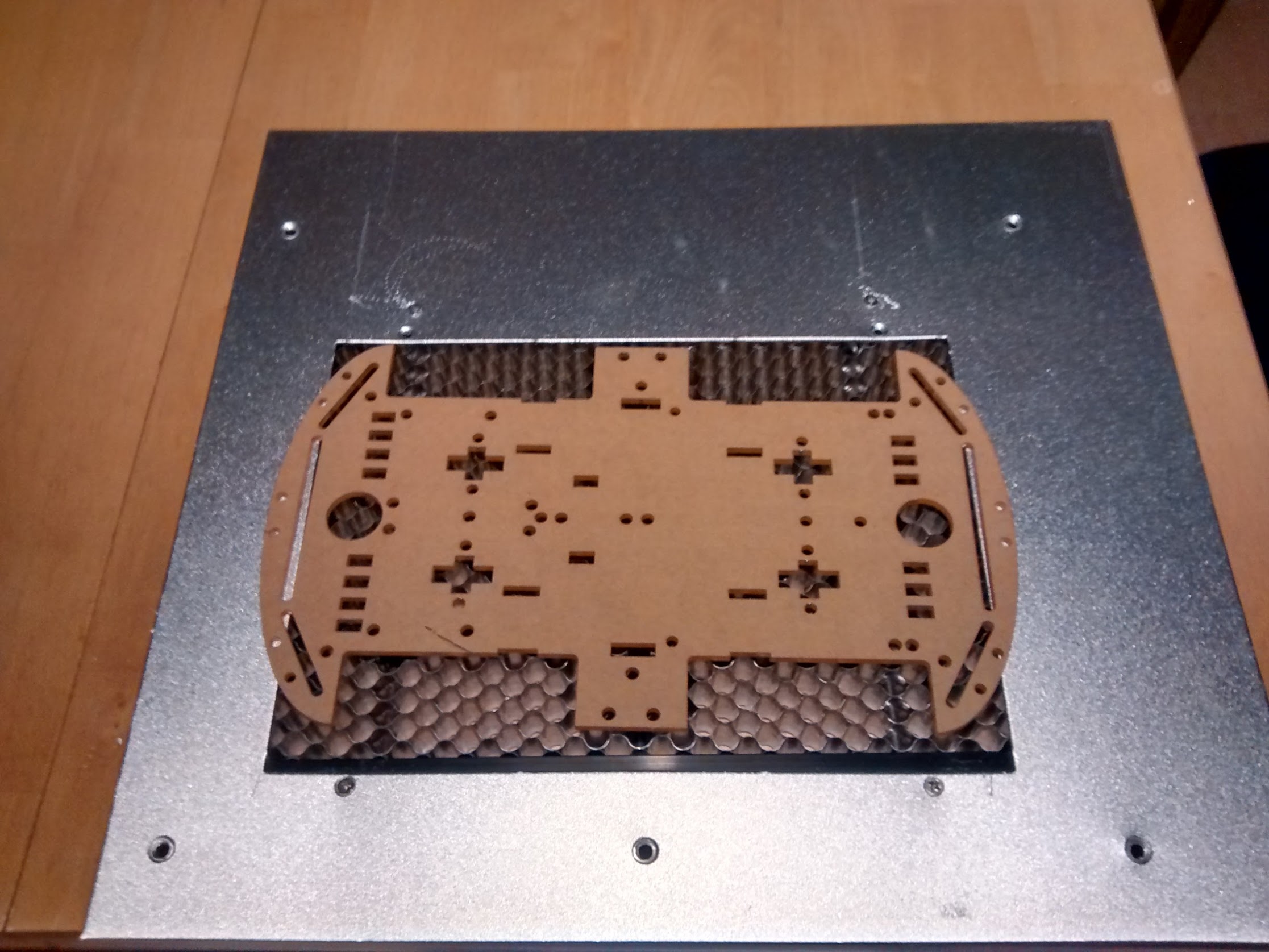
So I wasn’t going to fit the new honeycomb bed tonight but I did and managed to re-use the original screws. I can still remove some of the surround but that will require some (heavy) metal work and I am not sure I have any tools up to the task.
I think this probably will be ok for starters and I also have enough honeycomb lattice to make a new table that is as big as the cutter’s maximum reach, as per this: http://www.thingiverse.com/thing:273050
Laser Cutter Adventure – Part 3
So the cutter is now sited in the garage and awaiting its chiller, I thought I would have a look at installing the software and getting up to speed. The K40 comes with either Moshi Draw or Laser Draw (a plug-in for Corel as well as a standalone app). After hearing bad things about Moshi Draw I specifically brought a cutter that said it came with Corel, knowing Andy (the man with the broken cutter, ed.) used it I thought this might be best.
The install of Corel and Laser Draw went fine on a Windows 8 laptop, although I did enable windows XP SP3 compatibility for both. Laser Draw has a hardware dongle which seems petty since you can’t really use it without the cutter.
Unlike Andy’s cutter the K40 is does not appear to Windows as a printer and needs the Laser Draw plug-in to generate engraving, marking or cutting tasks. This video from BJ’s Wood Working was very handy:
Laser Cutter Adventure – Part 4
Its Alive!

Dear Laser, where have you put the text. Ah, OK, thx, bye.
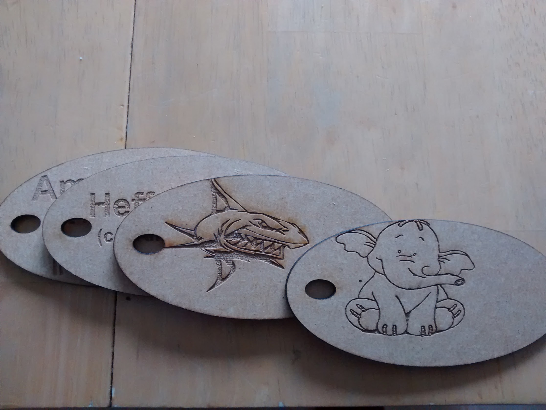
Some tweaking required! After a small amount of time playing with the cutter making name tags for Amy (Phil’s daugher and our team’s PiWars mascot, ed.) and Heffalump, I have discovered that the origin for cutting and engraving are different so some more work required to sort out what’s going on.
Also the original TractorBot design PDF’s don’t load into Corel. However, DXF files do so we should stick with DXF for the moment.
Laser Cutter Adventure – Part 5
Luggage Tag examples showing offset between cutter and engraving, these were printed after my first attempt at compensation!
Laser Cutter Adventure – Part 6
This image shows the 3D printed drag chain and red dot holder for the cutter. Just waiting for some hook up wire. Andy brought round a very nice compressor for my air assist, so the drag chain will hold both air line and the power for the red dot laser diode.

Ed: there was a stir in the Force when we all saw this. The 3D printer was making components for the laser cutter. It felt like some kind of line had been crossed and we were suddenly in a whole new landscape of possibility. I won’t lie, there was an actual few seconds of silent awe in the makerspace.
Laser Cutter Adventure – Part 7
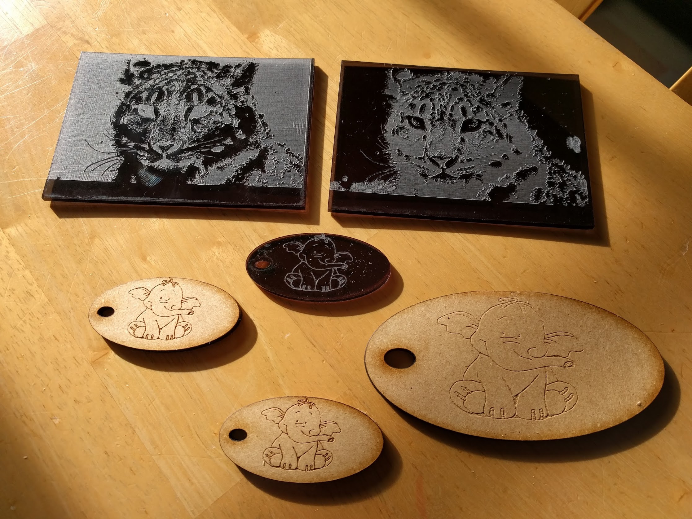
This morning I have been trying out different materials, power and speeds. I can cut the perspex at 5mm/s and 75% power and the engraving works quite well. Although the negative image of the snow leopard has some random blotches on it which I am not sure where they came from. Heffalump was engraved at 10, 20 and 30% power at 360mm/s ( the last on hardboard and perspex ).
Gift tags anyone?
The perspex cuts easier than ply 5mm/s and about 75% power. The air assist works really well on the hardboard not a flame to be seen!! Perspex engraves without any visible burn. The cut is ok as long as you remove the top protective layer but leave the bottom one on.
Laser Cutter Adventure – Part 8
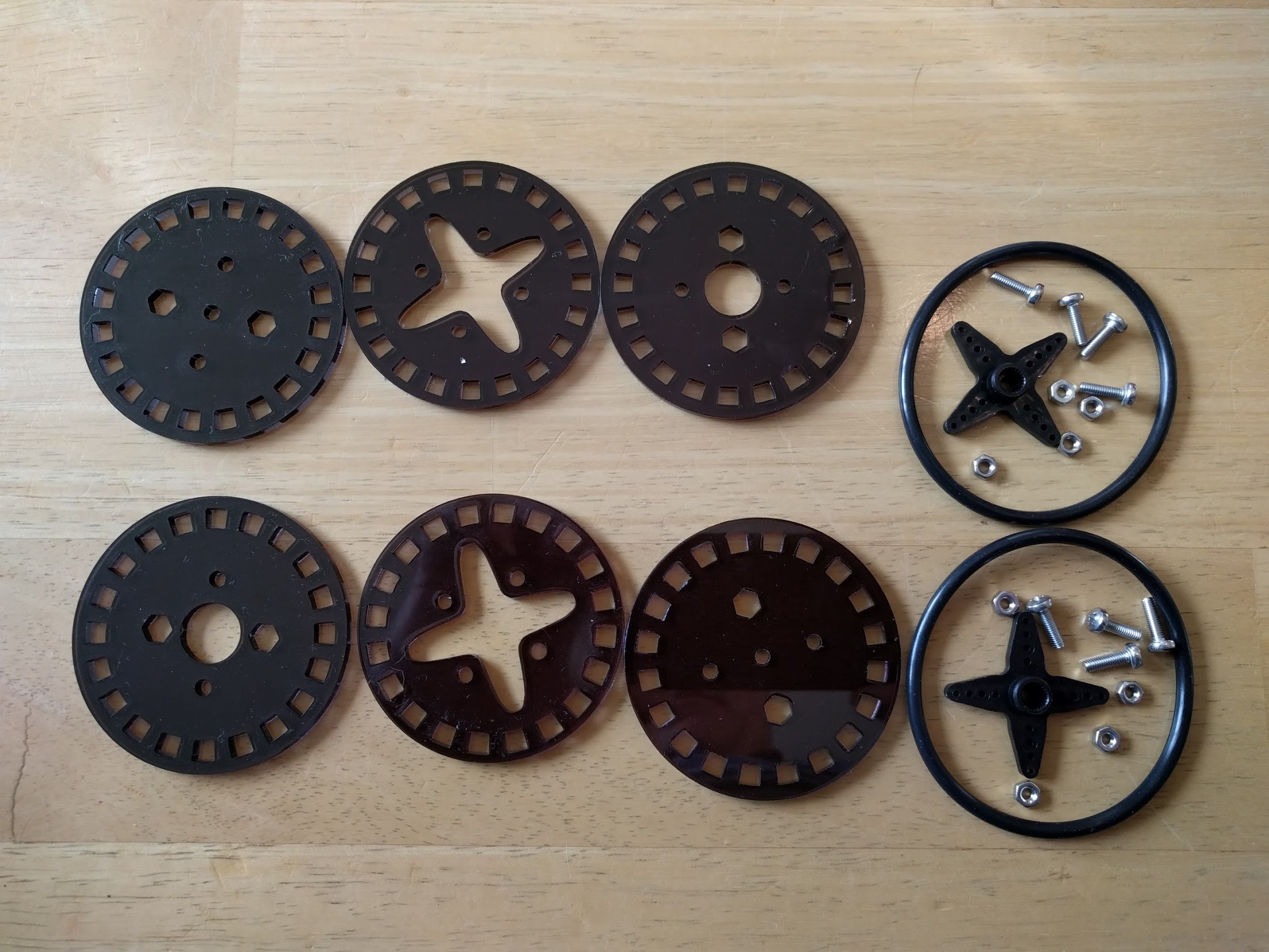
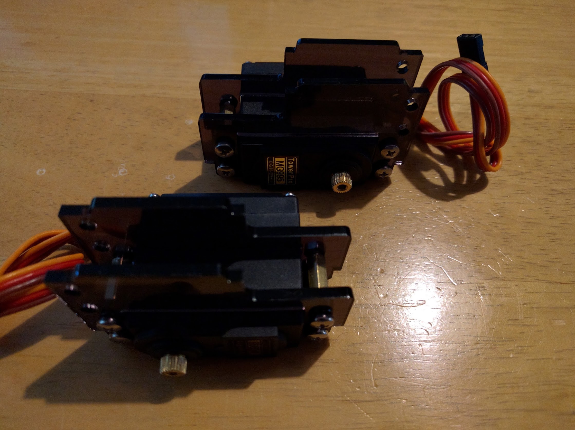
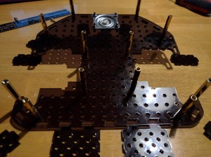
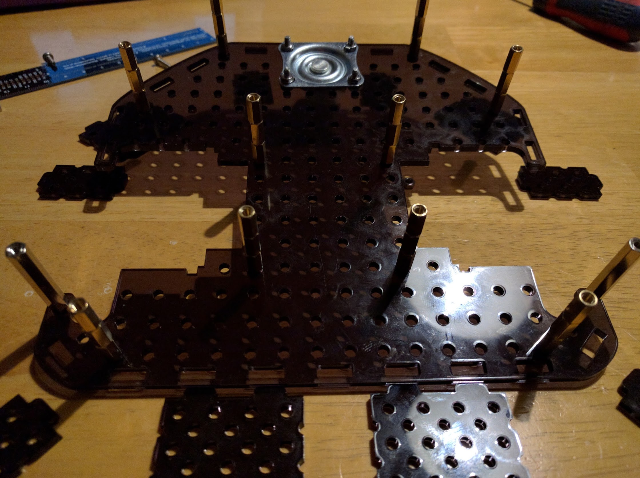
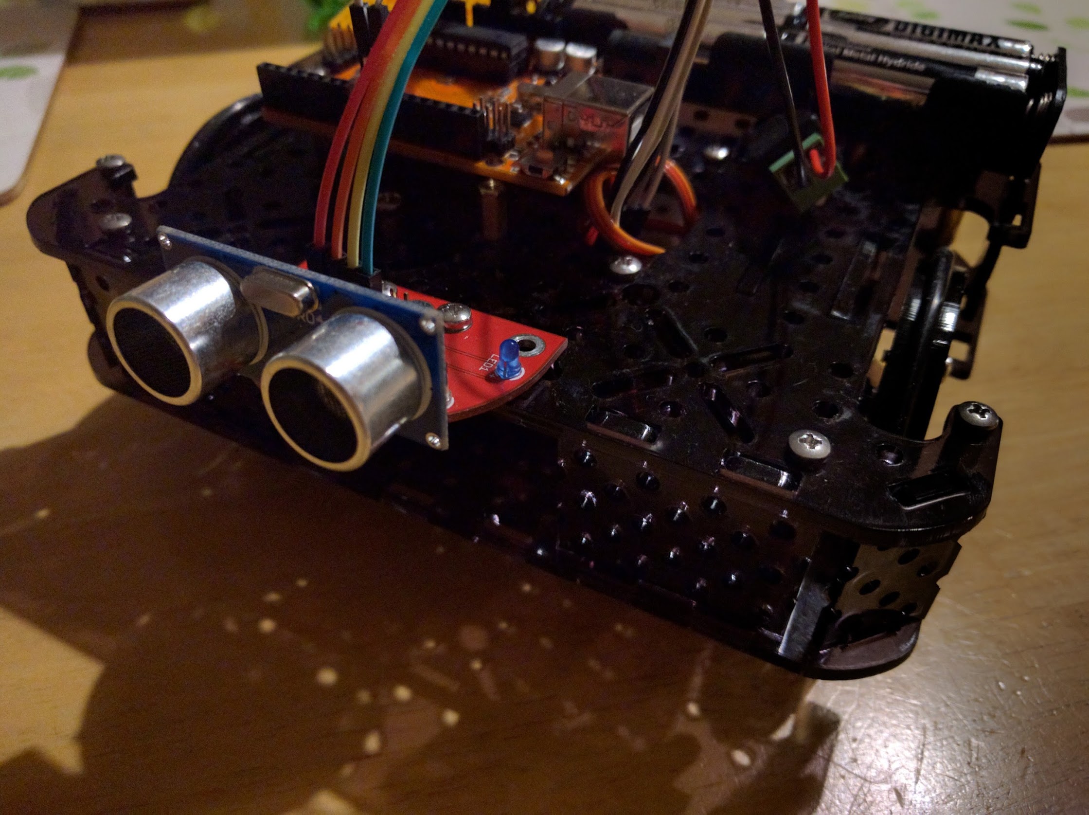
In this last set of images the body parts for a BaseBot have been cut out of all black acrylic. Amy instantly dubbed it Kiwi. It’s very impressive how fast a project like this can go from a download to a physical object wandering round the kitchen avoiding bumping into wall, cupboards etc. As a simple bot it’s been invaluable as a test bed for different facets of TractorBot anatomy and physiology. This one has a temporary Arduino clone in it while the Pi is in another TractorBot prototype. Thanks to the team at BaseBot and we’re all looking forward to seeing them at PiWars.
.

Final Word
Final Word
Ed: So there you have it, from disaster to triumph in one small blog. I’m sure we can cut a deal on the film rights if you’re interested. It has been a remarkable journey though, and Phil has been very dedicated and creative fettling his new machine. The 3D printed parts seem like an essential upgrade and the combo of laser and printer has allowed the team (Keith, Phil and Jon) to produce a very professional looking bot in my (Steve’s) opinion.
If you’re thinking of acquiring one of these machines then please be careful. Lasers are dangerous in a life-changing way and we’re suspicious of the value of the coloured plastic insert in this laser’s lid. It may, or may not, offer any protection from the scattered laser beam, and scattered laser light will damage your eyesight very effectively.
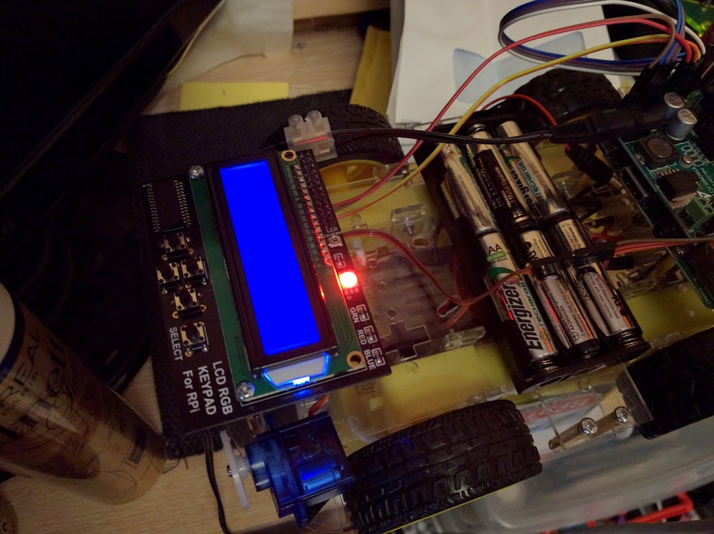
We have a robot
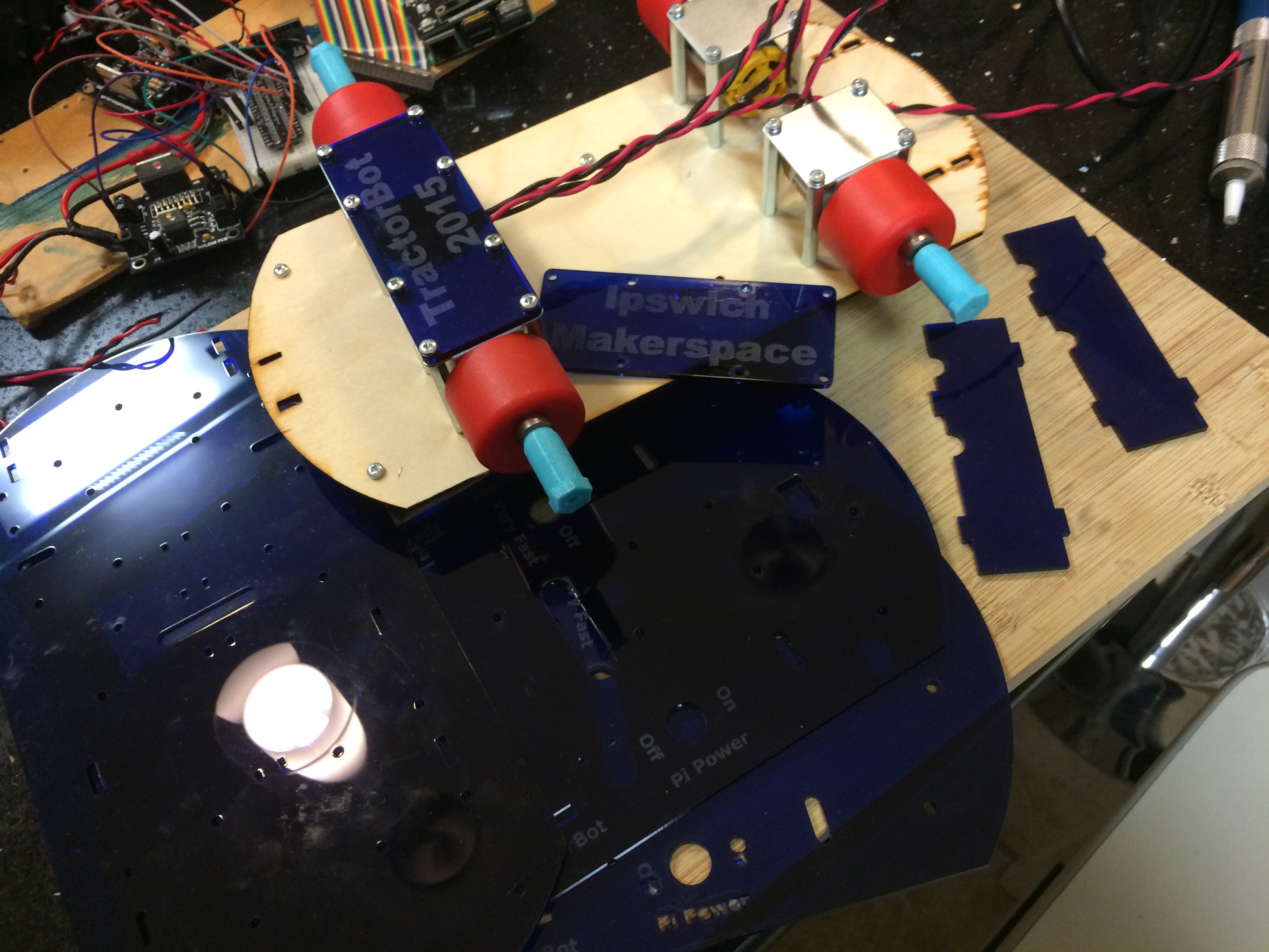
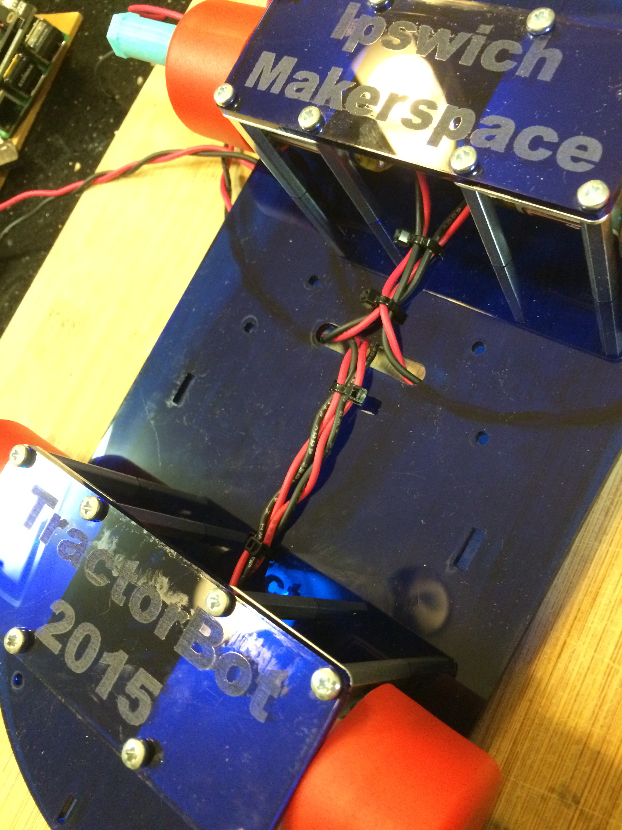
Keith Ellis : November 25, 2015 09:56 : PiWars 2015Just a quick post, last night was quite a moment for us. This week Keith and Phil have been working on the laser cut files and they have now been put together and we actually have a robot. TractorBot 2015 has left the virtual world and now actually exists in reality.
-
- Soldering thicker wires to the motors
-
- The laser cut parts have arrived
-
- Assembly starts, we even designed cable tie slots
-
- On goes the motor driver
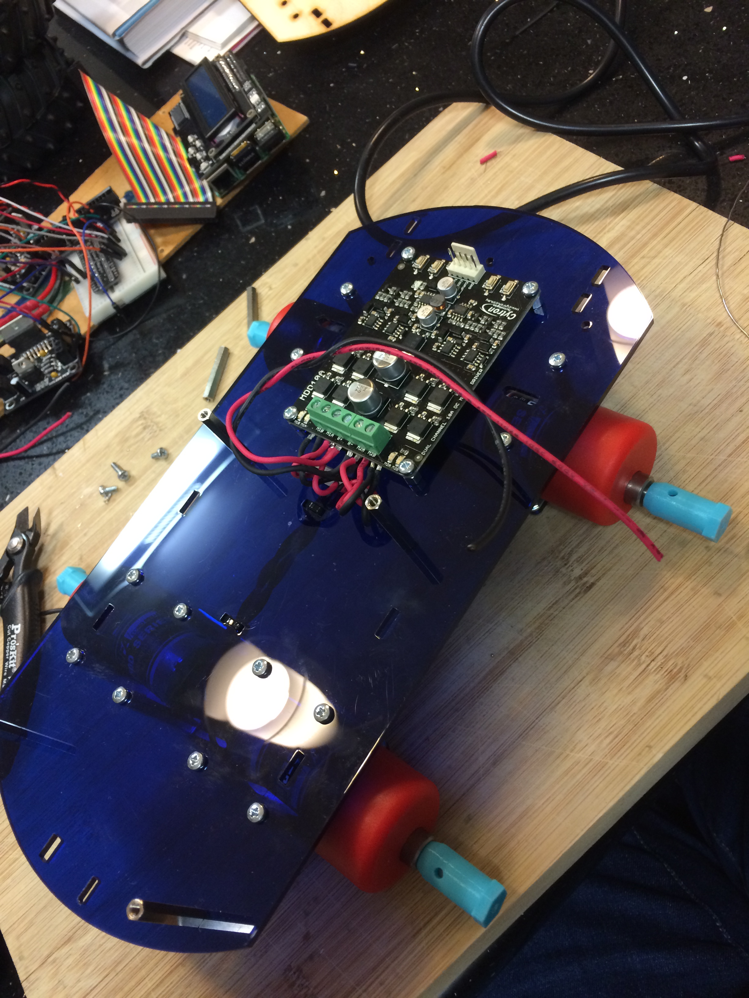
-
- Top plate goes on with switches
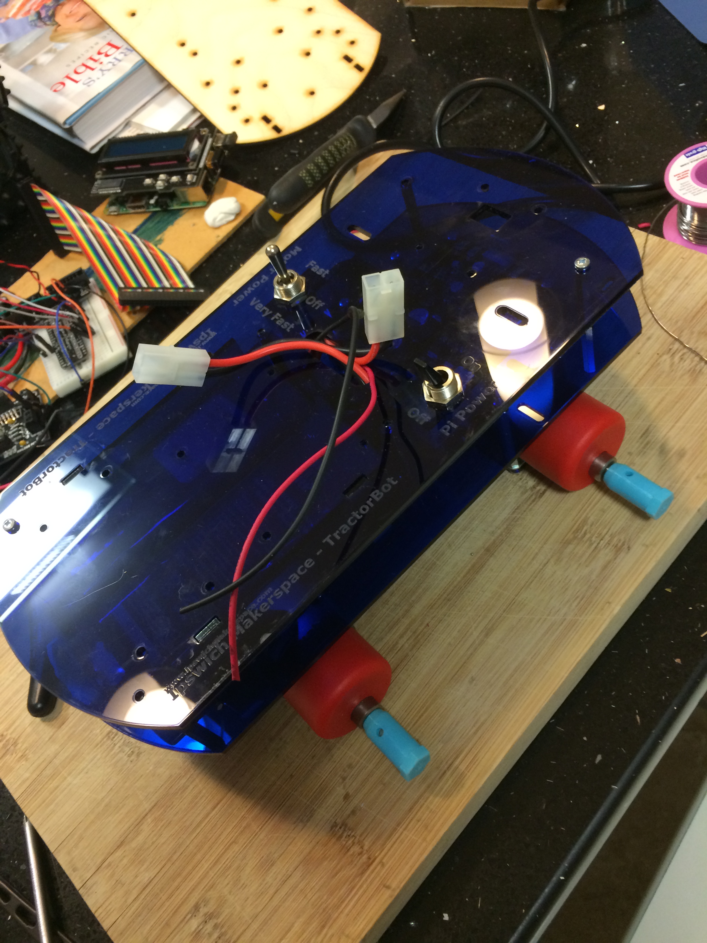
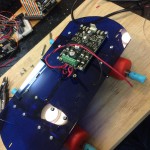
The almost completed robot
-

- Display, Pi and DC-DC convertor added
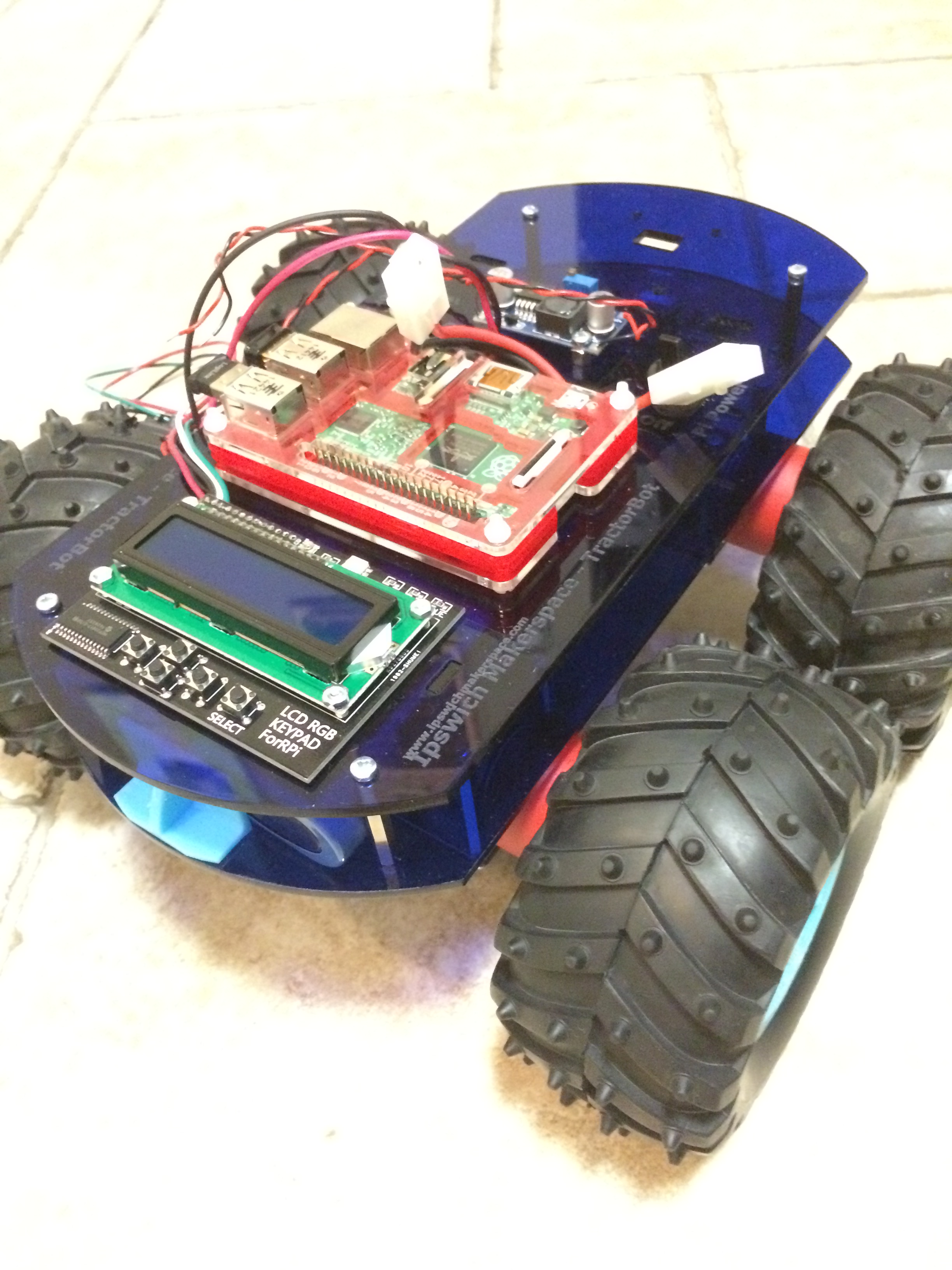
-
- More or less complete
-
- Looking awesome
Also going on this week, Jon has been working with the Hall Effect sensors and has created a library so the Pi can read the sensors via an Arduino Pro Mini clone. Along with this he has also been working on some PID (proportional, integral, derivative) code to allow TractorBot to drive in a straight line along with navigating the three point turn course. Jon just needs to tune it now so that it works with the competition bot seen above.
Phil has been fine tuning the line following code, but once again this really needs to be tuned on the competition robot.
Things that still need to happen. The robot has not moved yet, we are awaiting delivery of a couple of PCB’s, one to mount the line follow sensors and the second is the main interface board which hooks everything together. Hopefully these will be arriving today and maybe tonight TractorBot will move!
Keith also needs to convert the trial skittles ball launcher to fit the new robot and get the bits laser cut by Phil, the wire holder for the Pi Noon challenge needs to be designed and 3D printed, as do the wheel hub magnet mounts. Lots to do, now where is that Red Bull!
PCB’s
Keith Ellis : November 17, 2015 12:14 : PiWars 2015It’s been a while since the that post, largely due to getting the robot prepared. We still do not have a competition robot, we have a number of prototypes testing the code and various sensors, but the competition robot is still very virtual.
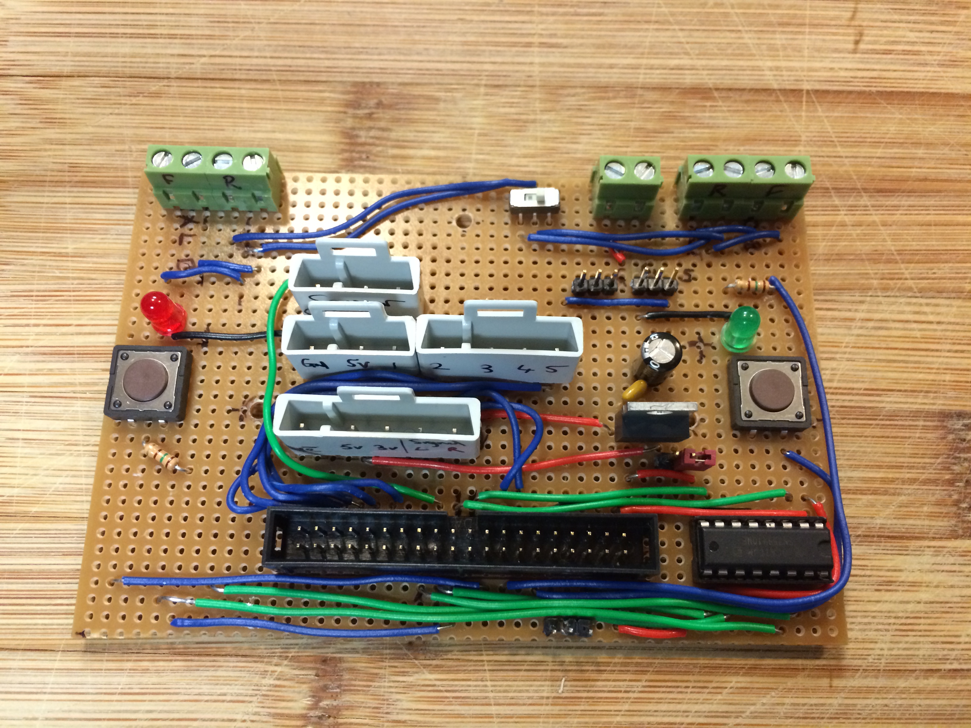
Last years interface board
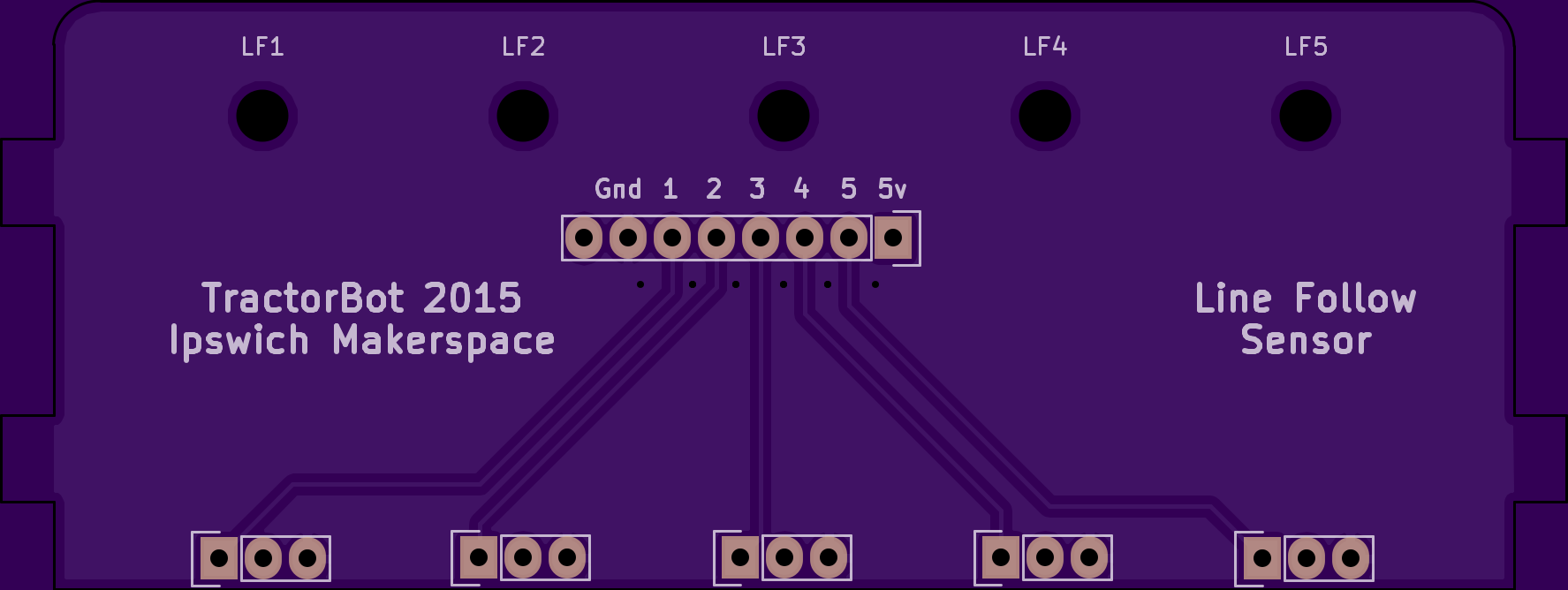
Line follower mounting PCB
Line sensor PCB mounted to chassis
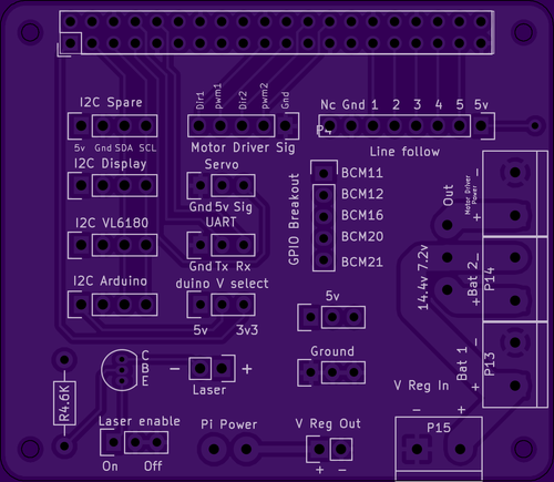
HAT style interface board
If all goes well we are expecting the line follower board at any time and the interface board early next week.
So next, probably most importantly is to make a physical robot. Over the next week Keith will be sending the laser cut and 3D print files to Phil so the robot can start to be assembled. Since this is already built in a 3D model environment it should not take too long, just a few tweaks here and there.
The main task is to convert the skittles ball launcher from 2D and get it in the 3D model so that a good fit can be ensured, oh, the trigger mechanism also needs to be designed. We still have three months to go, don’t we…
Jon is also working on the wheel encoder system, which this year we have decided to use Hall effect sensors and magnets, more on this in a later blog post.
Red light – Warning, laser enabled!
So it’s coming together and being tested on various prototypes, but it’s still a worry we don’t have a competition robot yet.
Now where did I put that time machine…
Code and 3D models
Keith Ellis : November 6, 2015 13:10 : PiWars 2015A lot has happened since the last blog post, but we still do not have much to show for it.
Jon has bee refining the proximity code along with his library for the VL6180 sensor. TractorBot now gradually reduces speed as an object is approached. Hopefully this will enable us to get extremely close. I’m still wondering how this be scored on the day, last year measuring the distances involved torches and calipers. Maybe this year feeler gauges would be useful.
Phil, has been doing a general tidy up to the code and refining it where necessary. We now have a different control system called “Tank Mode”, this allows us to use the two sticks on the Wii Classic controller to control the left and right motors individually in a skid steer manner.
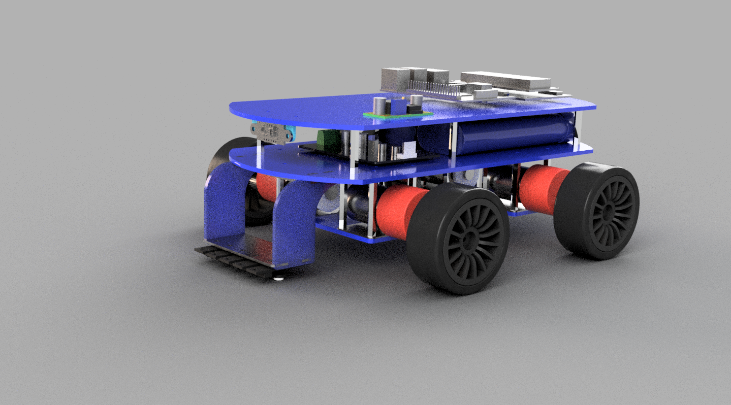
Keith has been producing fancy virtual images of what TractotBot 2015 might look like.
Fancy virtual model
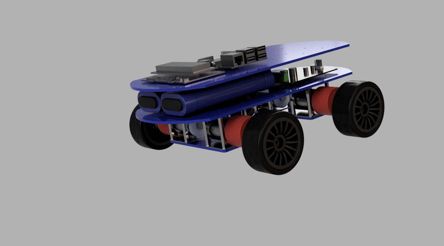 Whilst this looks very nice and has allowed Keith to design the robot in 3D ensuring all the parts fit together nicely, he was getting worried out how to make the virtual model a real one. It was simple to produce the STL files for the 3D printer but what was unclear was how to extract the data for the laser cut element. Anyhow, Keith plowed on, after all, the images did look very good.
The wheels described in the last post have now been refined and Phil dutifully printed them out. The quick time lapse below condenses the 13 hour print job into a few quick seconds.
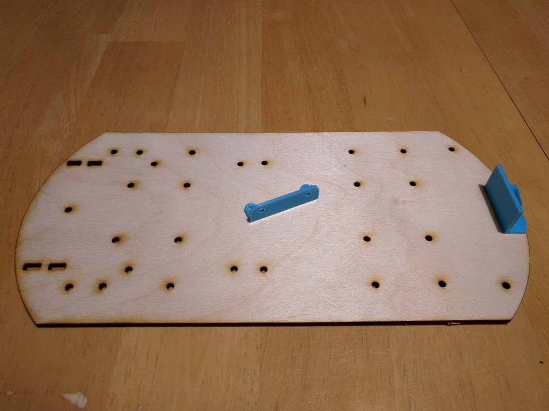
First laser cut elements
A couple of days ago though, it all came together, Keith discovered how to extract DXF files for the laser cut elements, they were sent off to Phil for checking and he was able to use them with his laser cutter setup. So now the 3D model can become reality. Producing 3D images can be invaluable for understanding how something goes together and for getting an understanding on how something will work prior to actually building it. But now we have the possibility of 3D printing and laser cutting the elements directly from 3D model the whole build process becomes much more simplified. Last year the battery was held in place with a hair band and some blutack, this year however we have custom laser cut and 3D printed parts.
The tool being used is AutoDesk Fusion 360, it is free for makers and tinkers and is quite easy to pick up and has some very good build in tutorials. It has software for OSX and Windows and there is an online collaboration element called A360 which enables team members to view and rotate the model and provide comments.
Over the next week or so, Keith will be finalising the design and sending the files to Phil for printing and cutting. Hopefully soon we shall have an actual TractorBot to test and complete the code refinements.
Wheels and 3D printers
Keith Ellis : October 27, 2015 11:12 : PiWars 2015Lots has happened this week, but time is rapidly running out!
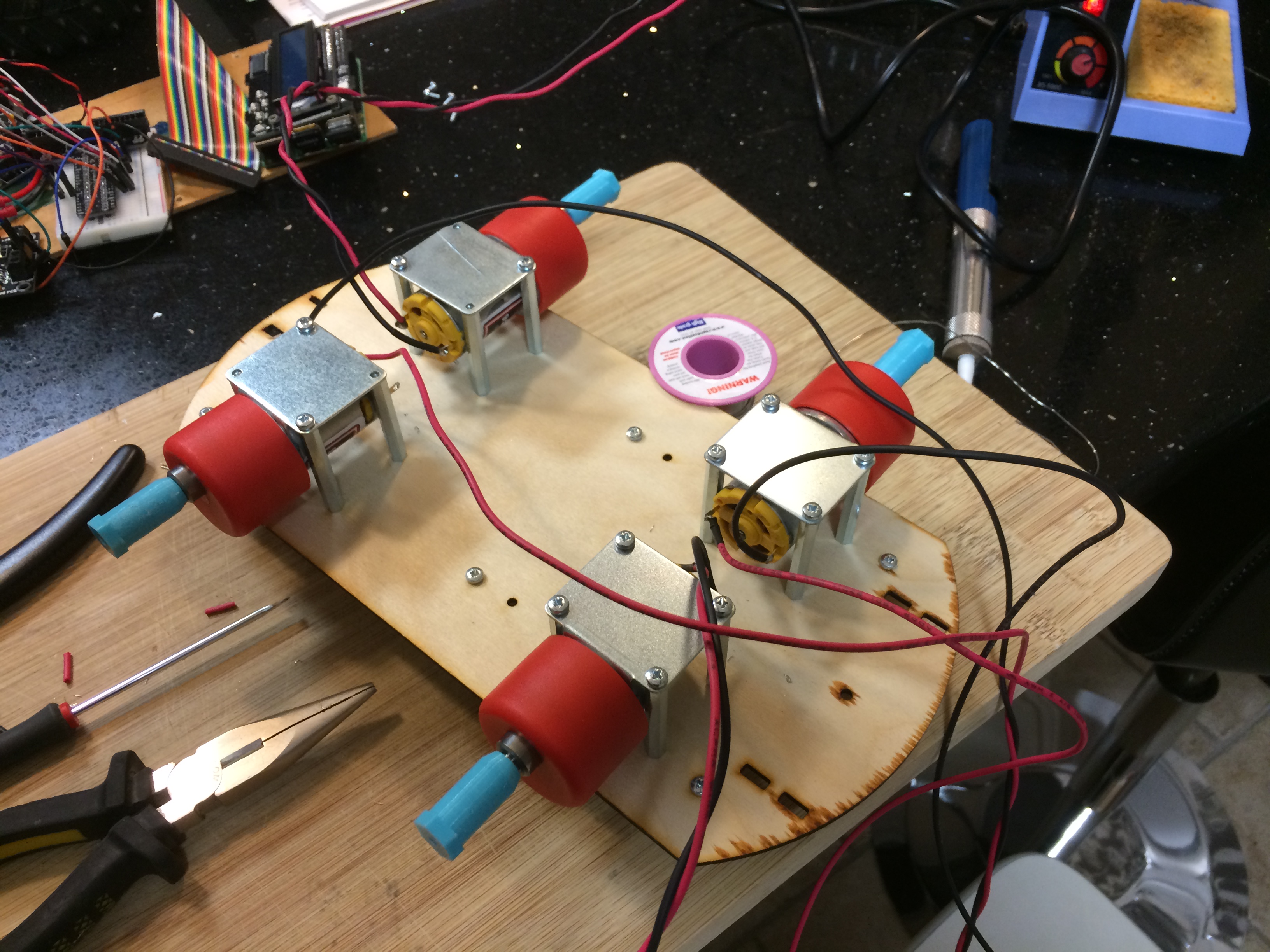
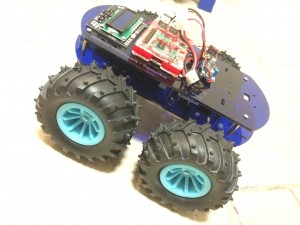
Last week we got TractorBot up and running with a hacked together chassis and did a comparison with last years entry. Something that became clear was the size, the new motors and large wheels made TractorBot 2015 wider than a sheet of A3 paper, thus too big to enter. There were a couple of options
- Revert to smaller motors
- Get smaller wheels
- Mount the motors closer together
- Modify the wheels to the offset was reduced
We really like the motors, they are not as fast as we hoped but are very powerful, therefore option 1 was out. The next three options however were all something we could work on.
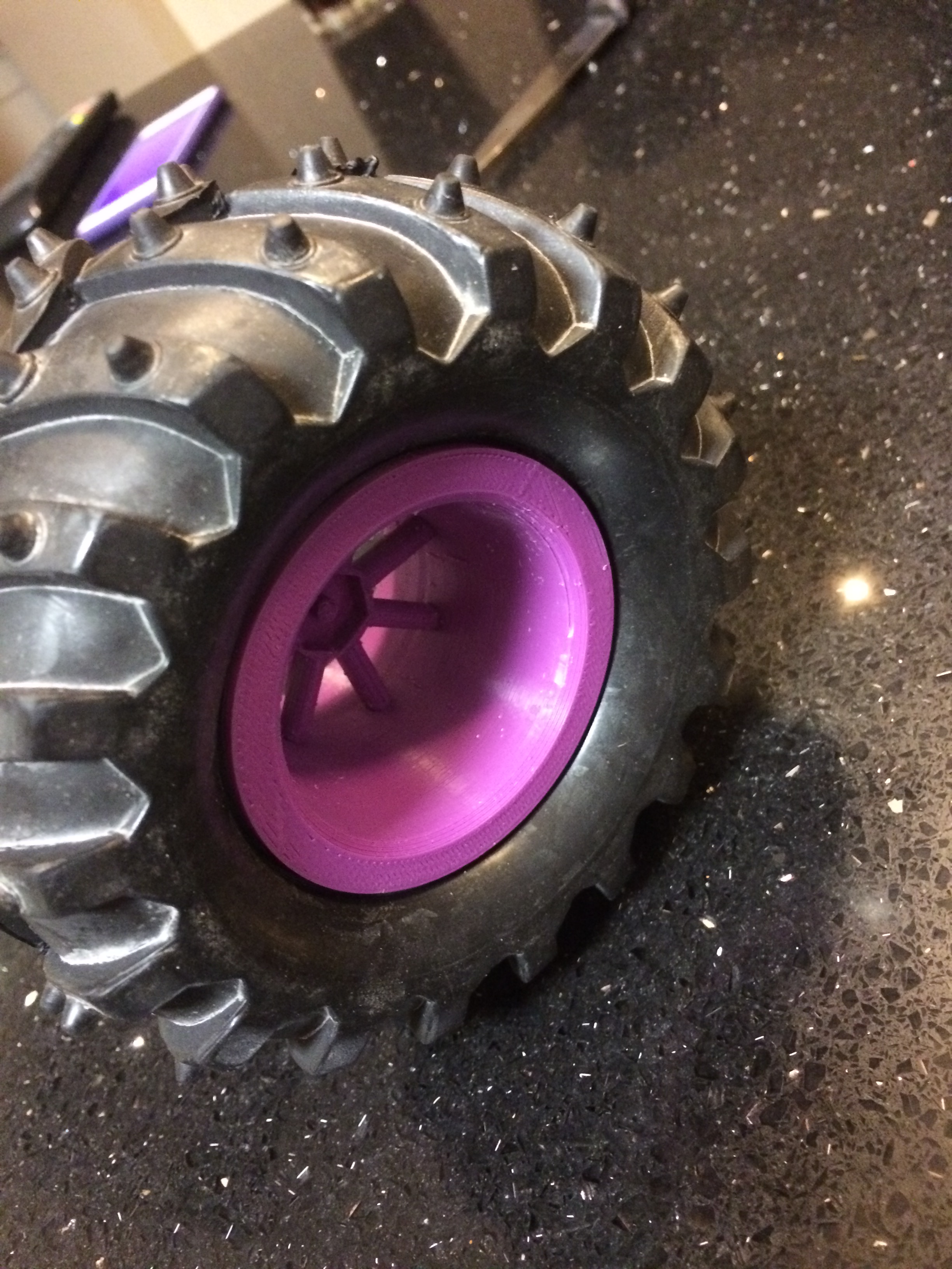
First we tried out the smaller wheels, the ones we tried were from Rapid. With luck they had the same size hexagonal hub so they fitted straight onto the 3D printed hub converters we had made for the larger wheels. The wheels were quickly fitted and went for a test drive.
Apart from looking very strange, TractorBot was obviously a bit slower due to the smaller wheel diameter, but this has added advantages. It made the bot much more controllable and very precises. We feel this will make for a very good platform for the precision events such as three point turn and the proximity challenge.
The next option was to mount the wheels closer together, this is an easy win and will be incorporated into the next chassis design, more on this in a later post.
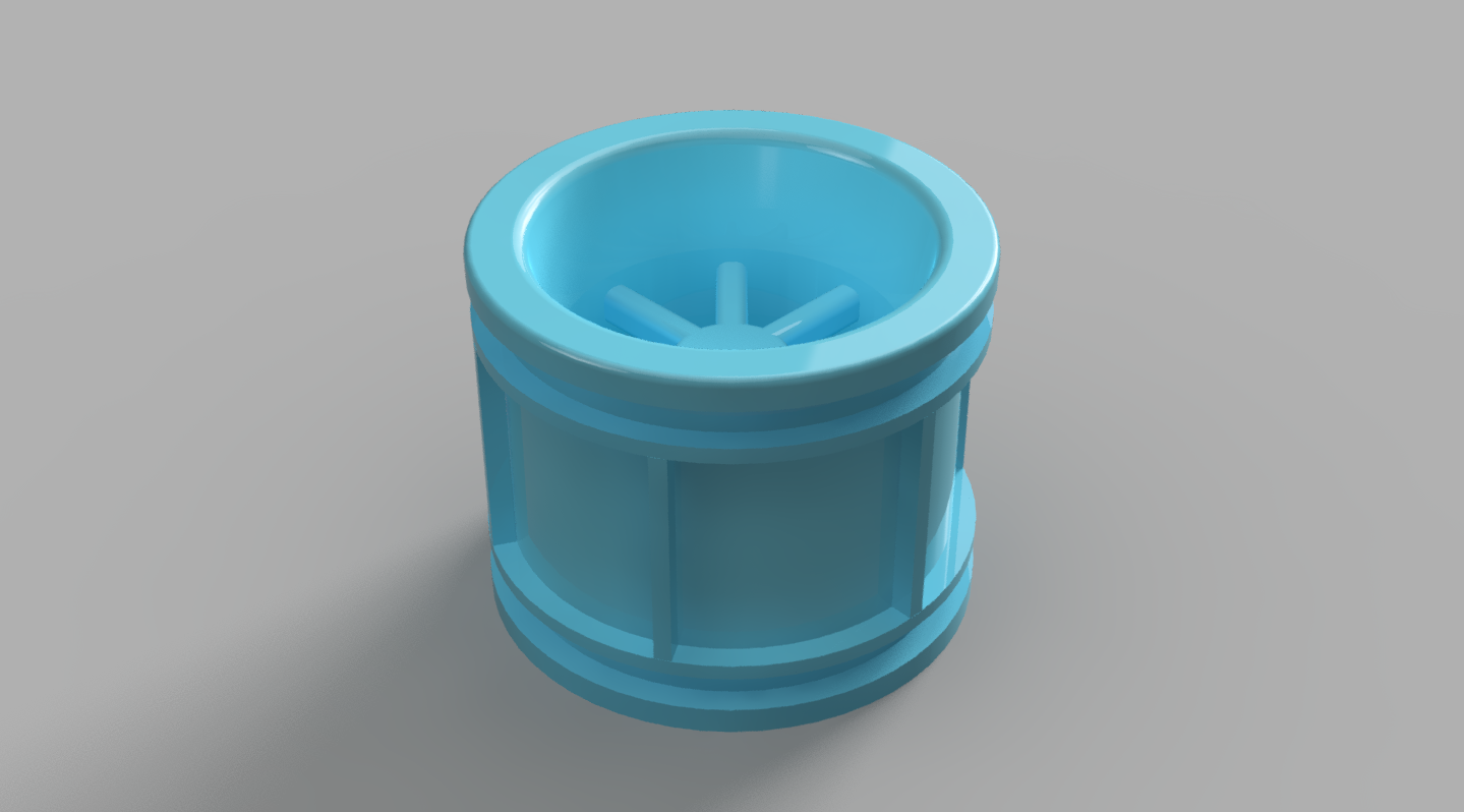
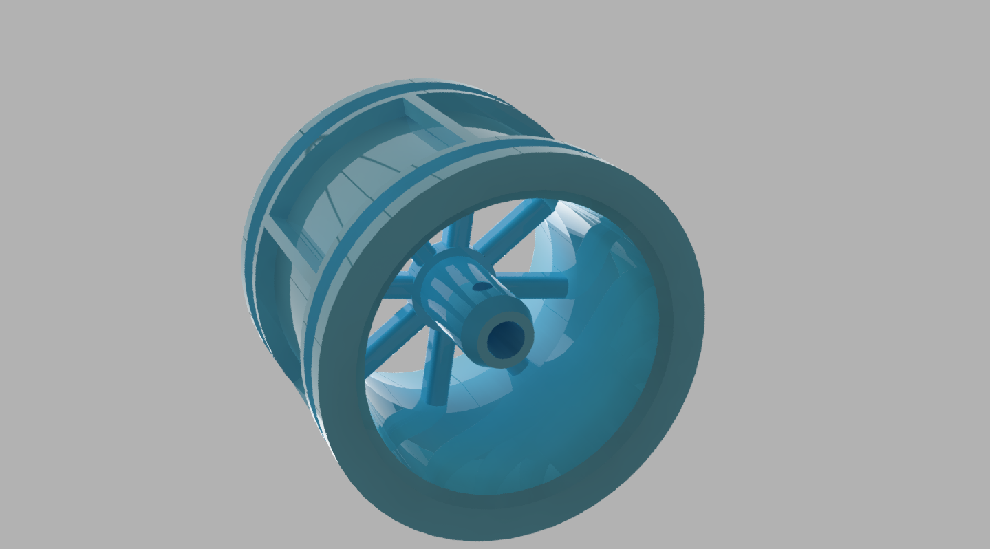
The final option would take a bit of effort but would help a lot in reducing the width of the bot. The current rims for the large wheels are designed in such a way that the whole wheel is offset to the outside of the hub fixing point. If the hub fixing point could be moved into the wheel then the wheel would start to overlap the motor shaft and create a smaller offset and thus a narrower bot.
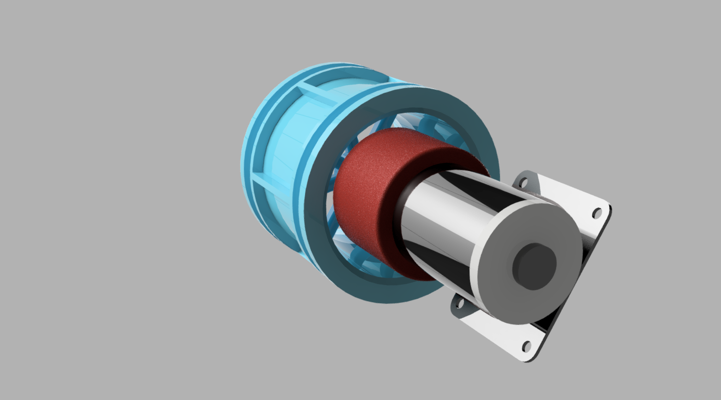
Since Phil had a 3D printer, Keith went off to design a new wheel, so out came the vernier gauge, off came the tyres from the original wheel and Keith duplicated the current wheel design into AutoDesk Fusion 360, this is free for makers and tinkerers and has some very nice features. The motors and hub adapter has already been modeled so Keith could put the three items together to make sure it all fitted together nicely.
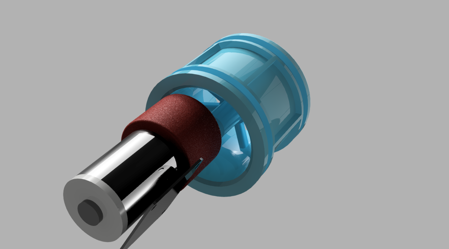
-

- Wheel hub and motor
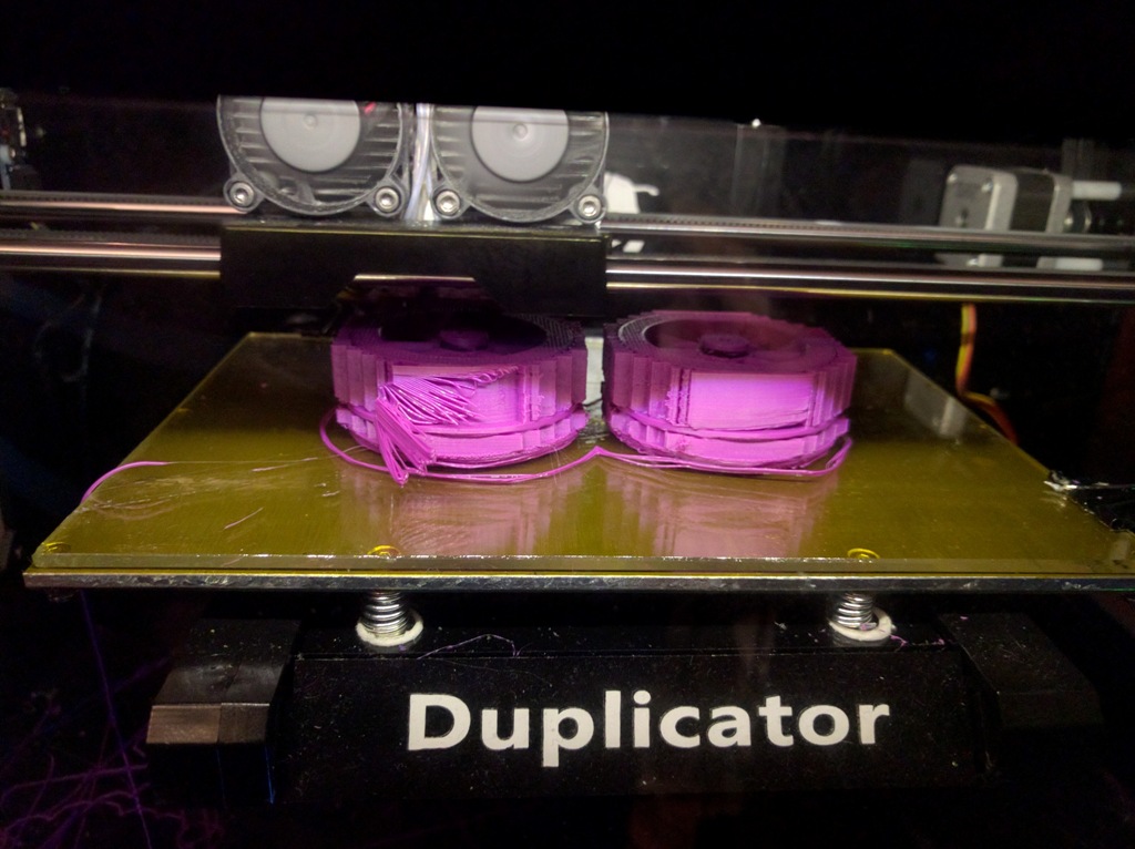 Everything looked like it was going to work so the STL file was created and sent off to Phil for printing. The printer was set running, it was a mammoth job and the software predicted that two wheels would take eight hours. The print button was pressed late one evening and left to run over night. Morning came and this was the result, just over half way through. It was lunch time buy the time they had finished.
Keith learned quite a bit about how to produce a 3D printable optimised model, if we get time we will blog about this separately. But for now, the wheel basically works and gives the desired effect.
-
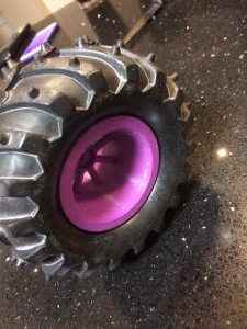
- The tyres fit
-

- Original wheel at the back, 3D printed wheel with smaller offset in the foreground
In summary, we now have a plan for making TractorBot fit within the size categorie for PiWars. Whilst doing so we have discovered we can 3D print our own wheels to our own specification and make them fit the tyres we already had. We also discovered that the robot was much more precise with smaller wheels. As such we now have the option to switch and change wheels to suit the task in hand. So now we need to carry on with the chassis design and start with the electronics. So much to do and so little time to do it.