OK so I’m really going off on a tangent now… I have decided to work out how the controller of my heating system works, and to a smart modification. This is likely pt1 of 2.
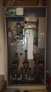
Here is the system, the wonderful Boilermate 2000.
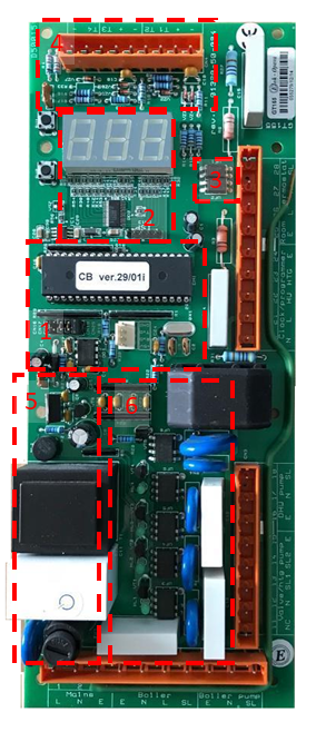
| In the top left is the PCB that runs the various pumps and things. These have a habit of failing every year or so, so I have built up a small collection of partially failed boards. I decided to attempt to work out how they worked and see what hacks I could do to them. This board is responsible for taking an input switched live signal from an external thermostat, monitoring the hot water tank temperature, controlling the Boiler, Boiler Pump, DHW pump and Central Heating pump.
This is a GT155 with the updated LED display driver. This one suffered from not being able to turn the DHW pump fully on, I think a triac has failed, but I don’t really know how to test it and to watch me desolder anything is like watching a lion pull the carcass of an antelope out of the passenger door of a nissan micra whilst balanced on a cliff top – like at the end of the Italian job. It’s dangerous, messy and probably doesn’t end well for anyone. Let’s talk through what we have here. |
Let’s take an in-depth look at some of these components.
Main CPU
The main CPU is a AT89C55 8-bit microcontroller with 20K of flash with 32 I/O lines. It is in PDIP configuration and socketed for easy extraction (he says instantly bending 4 of the pins).
X5045P
I misunderstood what this was a first, I thought it was just an EEPROM and tried to interface with it using SPI to read its contents. After a couple of hours failing at that, I actually looked at the datasheet and followed the traces again to discover that in fact it is a CPU supervisor (with some EEPROM) and that it was just being used to keep the CPU reset if the Vcc was below Vtrig, some kind of low voltage protection mechanism.
Jumpers
These configure the programme for various Boilermate systems
- Boilermate III with jumpers in position J4
- Systemate III with jumpers in positions J3 & J4
- Systemate 2000 with jumpers in positions J1 & J4
- Electramate 2000 170/9kW and 270/9kW with jumpers in positions J2 & J4
- Boilermate 2000 the jumpers are on positions J1, J3 & J4.
This PCB will fit the units above and can be used in place of GD131 – This model also fits other products but will need the jumpers re-configuring to suit the application.
LED display
This is a Kingbright display, it usually says “- on” or “= on” but can display diagnostic information via the 2 push buttons next to it
LED driver
On my GT155 this is [4] a P89LPC932A1, I assumed it had been programmed to interface with the LED display and take input from the main CPU. I traced 2 wires between this and the main CPU but couldn’t work out how it was being controlled (as I don’t have the right equipment mostly). That was until I got hold of a GD131, which is essentially the same PCB except it has one less output (vt4) and has a different LED driver, it has [5] a M5480 LED display driver, which will drive 23 segments with brightness control. Since the main CPU on both these 2 board had the same software version sticker on them I could only conclude that the P89LPC932A1 was mimicking the behavior of the M5480. I guess Gledhill decided to change to a cheaper or more available chip and update the design a bit without needing the change the main software. This was helpful and now I had documentation on the serial interface to control the LED driver.
Opto-isolators
These 2 opto isolators are Sharp PC814 “AC Input Photocouplers”. They are 1-channel with 5000Vrms isolation. UF1 is wired to Room Thermostat, UF2 is wired to the HW clock programmer.
Temperature Sensors
The temperature sensors have a bunch of supporting components, diodes, resistors, capacitor. They each take 5V, GND and return a temperature signal. I have yet to reverse engineer this, but I suspect they are DHT11 or DHT22. I havn’t bought one [8] yet to take apart.
PSU
Section 5 is all power supply type things, a fat looking diode, capacitor and transformer. It also includes a transistor that is switched on by the 5V power supply, which in turn makes a GPIO pin HIGH on the CPU. I don’t yet know what purpose this serves, maybe some kind of dying gasp.
Outputs
This is where the magic happens. 5 outputs are wired via resistors, with capacitors each to a transistor [VT1 to VT5] and LED which in turn enables a triac. When the GPIO output is LOW the triac turns on.
VT1 = Boiler
VT2 = Boiler Pump
VT3 = Heating Pump
VT4 = Hot Water Pump
VT5 = Not sure, seems to connect back to Neutrals of the Optoisolators via a fat Filtana inductor / capacitor, not sure what function it serves.
Reverse engineered CPU
I have traced out the pins from the CPU to the various components as follows:
Arduino Hack
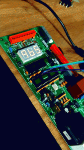
After ripping out the main cpu I wired an Arduino on the LED CLK and LED TX pins are started to attempt to drive the LED display. Once I worked out which segments where driven by which bit, it wasn’t hard to define the patterns to display numbers.
#notadeveloperbytradedontjudgeme 🙂 I’m looking for feedback on how to make this neater, because this is all a bit arse.
#define CLOCK_1 7
#define DATA_1 8
void setup() {
pinMode(CLOCK_1, OUTPUT);
pinMode(DATA_1, OUTPUT);
}
int current_numberToDisplay = 0;
bool DigitA[10][35] =
{ { 1,0,0,1,1,1,1,0,0,0,0,0,0,0,0,0,0,0,0,0,0,0,0,0,0,0,0,0,0,0,0,0,0,1,1 },
{ 1,0,0,0,1,0,1,0,0,0,0,0,0,0,0,0,0,0,0,0,0,0,0,0,0,0,0,0,0,0,0,0,0,0,0 },
{ 1,0,1,0,0,1,1,0,0,0,0,0,0,0,0,0,0,0,0,0,0,0,0,0,0,0,0,0,0,0,0,0,0,1,1 },
{ 1,0,1,0,1,1,1,0,0,0,0,0,0,0,0,0,0,0,0,0,0,0,0,0,0,0,0,0,0,0,0,0,0,1,0 },
{ 1,0,1,1,1,0,1,0,0,0,0,0,0,0,0,0,0,0,0,0,0,0,0,0,0,0,0,0,0,0,0,0,0,0,0 },
{ 1,0,1,1,1,1,0,0,0,0,0,0,0,0,0,0,0,0,0,0,0,0,0,0,0,0,0,0,0,0,0,0,0,1,0 },
{ 1,0,1,1,1,1,0,0,0,0,0,0,0,0,0,0,0,0,0,0,0,0,0,0,0,0,0,0,0,0,0,0,0,1,1 },
{ 1,0,0,0,1,1,1,0,0,0,0,0,0,0,0,0,0,0,0,0,0,0,0,0,0,0,0,0,0,0,0,0,0,0,0 },
{ 1,0,1,1,1,1,1,0,0,0,0,0,0,0,0,0,0,0,0,0,0,0,0,0,0,0,0,0,0,0,0,0,0,1,1 },
{ 1,0,1,1,1,1,1,0,0,0,0,0,0,0,0,0,0,0,0,0,0,0,0,0,0,0,0,0,0,0,0,0,0,0,0 } };
bool DigitB[10][35] =
{ { 1,0,0,0,0,0,0,1,0,0,0,0,1,1,0,0,0,0,0,0,0,0,0,0,0,0,0,1,0,0,1,1,0,0,0 },
{ 1,0,0,0,0,0,0,0,0,0,0,0,0,1,0,0,0,0,0,0,0,0,0,0,0,0,0,1,0,0,0,0,0,0,0 },
{ 1,0,0,0,0,0,0,0,1,0,0,0,1,1,0,0,0,0,0,0,0,0,0,0,0,0,0,0,0,0,1,1,0,0,0 },
{ 1,0,0,0,0,0,0,0,1,0,0,0,1,1,0,0,0,0,0,0,0,0,0,0,0,0,0,1,0,0,1,0,0,0,0 },
{ 1,0,0,0,0,0,0,1,1,0,0,0,0,1,0,0,0,0,0,0,0,0,0,0,0,0,0,1,0,0,0,0,0,0,0 },
{ 1,0,0,0,0,0,0,1,1,0,0,1,1,0,0,0,0,0,0,0,0,0,0,0,0,0,0,1,0,0,1,0,0,0,0 },
{ 1,0,0,0,0,0,0,1,1,0,0,1,1,0,0,0,0,0,0,0,0,0,0,0,0,0,0,1,0,0,1,1,0,0,0 },
{ 1,0,0,0,0,0,0,0,0,0,0,0,1,1,0,0,0,0,0,0,0,0,0,0,0,0,0,1,0,0,0,0,0,0,0 },
{ 1,0,0,0,0,0,0,1,1,0,0,0,1,1,0,0,0,0,0,0,0,0,0,0,0,0,0,1,0,0,1,1,0,0,0 },
{ 1,0,0,0,0,0,0,1,1,0,0,0,1,1,0,0,0,0,0,0,0,0,0,0,0,0,0,1,0,0,0,0,0,0,0 } };
bool DigitC[10][35] =
{ { 1,0,0,0,0,0,0,0,0,0,0,0,0,0,1,0,0,0,0,0,1,1,1,1,1,0,0,0,0,0,0,0,0,0,0 },
{ 1,0,0,0,0,0,0,0,0,0,0,0,0,0,0,0,0,0,0,0,0,1,1,0,0,0,0,0,0,0,0,0,0,0,0 },
{ 1,0,0,0,0,0,0,0,0,0,0,0,0,0,0,1,0,0,0,0,1,1,0,1,1,0,0,0,0,0,0,0,0,0,0 },
{ 1,0,0,0,0,0,0,0,0,0,0,0,0,0,0,1,0,0,0,0,1,1,1,1,0,0,0,0,0,0,0,0,0,0,0 },
{ 1,0,0,0,0,0,0,0,0,0,0,0,0,0,1,1,0,0,0,0,0,1,1,0,0,0,0,0,0,0,0,0,0,0,0 },
{ 1,0,0,0,0,0,0,0,0,0,0,0,0,0,1,1,0,0,0,0,1,0,1,1,0,0,0,0,0,0,0,0,0,0,0 },
{ 1,0,0,0,0,0,0,0,0,0,0,0,0,0,1,1,0,0,0,0,1,0,1,1,1,0,0,0,0,0,0,0,0,0,0 },
{ 1,0,0,0,0,0,0,0,0,0,0,0,0,0,0,0,0,0,0,0,1,1,1,0,0,0,0,0,0,0,0,0,0,0,0 },
{ 1,0,0,0,0,0,0,0,0,0,0,0,0,0,1,1,0,0,0,0,1,1,1,1,1,0,0,0,0,0,0,0,0,0,0 },
{ 1,0,0,0,0,0,0,0,0,0,0,0,0,0,1,1,0,0,0,0,1,1,1,0,0,0,0,0,0,0,0,0,0,0,0 } };
bool LetterC[35] = { 1,0,0,0,0,0,0,0,0,0,0,0,0,0,1,0,0,0,0,0,1,0,0,1,1,0,0,0,0,0,0,0,0,0,0 };
void showTemp(int numberToDisplay)
{
bool output[35] = { 1,0,0,0,0,0,0,0,0,0,0,0,0,0,0,0,0,0,0,0,0,0,0,0,0,0,0,0,0,0,0,0,0,0,0 };
int A = (numberToDisplay / 10) % 10;
int B = (numberToDisplay) % 10;
for (int i = 0; i < 36; i++)
{
if (LetterC[i] == 1) { output[i] = LetterC[i]; }
if (DigitB[B][i] == 1) { output[i] = DigitB[B]; }
if (DigitA[A][i] == 1) { output[i] = DigitA[A]; }
}
for (int i = 0; i < 36; i++)
{
digitalWrite(CLOCK_1, LOW);
delay(1);
digitalWrite(DATA_1, output[i]);
delay(1);
digitalWrite(CLOCK_1, HIGH);
}
}
void showNumber(int numberToDisplay)
{
bool output[35] = { 1,0,0,0,0,0,0,0,0,0,0,0,0,0,0,0,0,0,0,0,0,0,0,0,0,0,0,0,0,0,0,0,0,0,0 };
int A = (numberToDisplay / 100) % 10;
int B = (numberToDisplay / 10) % 10;
int C = (numberToDisplay) % 10;
for (int i = 0; i < 36; i++)
{
if (DigitC[C][i] == 1) { output[i] = DigitC[C]; }
if (DigitB[B][i] == 1) { output[i] = DigitB[B]; }
if (DigitA[A][i] == 1) { output[i] = DigitA[A]; }
}
for (int i = 0; i < 36; i++)
{
digitalWrite(CLOCK_1, LOW);
delay(1);
digitalWrite(DATA_1, output[i]);
delay(1);
digitalWrite(CLOCK_1, HIGH);
}}
void loop()
{
showTemp(65);
}
The result
The output looks a little something like this. I can drive digits on the display! I can detect input from the optoisolators, drive the triacs on and off. The arduino has no use for the X5045P nor the serial port really.
The temperature sensors GT153 are still a mystery until I decide to part with £23 to buy one to play with. [8]
Boilermates HAT
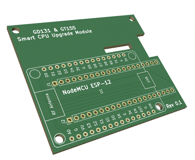
It seemed only logical the next step was to design a “HAT” for the GT155 (and GD131). I needed more GPIO than my NodeMCU 0.9 would care to give me, so I have opted for the 23017 GPIO expander.
The PCB looks like this right now, with slots cut out for the LED driver ISP header and to avoid 2 capacitors. More work needs to be done to optimise, as there are too many tracks under the wifi antenna and the USB port is too close to other components to get the cable in whilst attached.
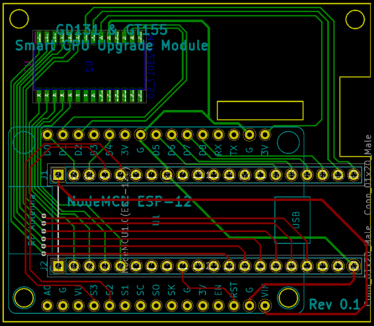
It looks a bit like this in 3D. The 23017 is hiding on the back.
Final words.
This was the culmination of a years effort (on and off) to work out how these PCBs fail and attempt to use them for something interesting. I spent xmas 2017 with the flu with no heating due to a GT155 failing, so it was about time I got my revenge on it and forced it to release its secrets.
The GT152 is a mini version of the board, it just acts as a pump controller but with much the same architecture, 2 temperature sensors and a triac driving the output. Once I have a prototype of one of these boards confirmed working, anyone who wishes to start hacking with these board can contact me and I can provide the schematic files or some spare boards.
I really need to study the operation of the GT155 PCB to see what functions it performs, such as
- Keeping the water tank at the right temperature
- Responding to Thermostat Switched Live
- Responding to Direct Hot Water (Temperature Drop in Heat Exchanger?)
- Switching on Heating Pumps
- Switching on Boiler and Pumps
As I need to be able to safely operate the system with my own code without blowing up my boiler or pumping scolding hot water around the house 🙂 I dont know if I can recover a dump of the program from the AT89C55, I doubt it. Maybe the kind people at Gled hill will give me it 🙂 (not).
Some of the benefits that could be realised from this project:
- Data / IFTTT notifications from the system regarding water tank temperature, pump activations etc.
- Direct control to switch on/off system (Alexa etc.)
- Interface directly to WiFi Smart Thermostatic Radiator Valves (remove wired thermostat) to create cost effective zoning (if I can find some) or via a controller / gateway.
I provide no warranty with these instructions and any result of you making these modifications is not my responsibility. Making modifications such as these to your boilermate 2000 or any other boiler will invalidate any warranty it has, invalidate your boiler cover, invalidate any warranty for any work you had done on it, invalidate your house and contents insurance and will likely cause harm to puppies and kittens and cause you to instantly void your bowels. You have been warned.
Datasheet references
[1] http://www.keil.com/dd/docs/datashts/atmel/doc0580.pdf
[2] https://www.digikey.co.uk/product-detail/en/renesas-electronics-america-inc/X5045P/X5045P-ND/387248
[3] http://www.kingbrightusa.com/images/catalog/SPEC/BA56-11EWA.pdf
[4] http://pdf.datasheetcatalog.com/datasheet/NXP_Semiconductors/P89LPC932A1.pdf
[5] https://www.st.com/resource/en/datasheet/cd00019020.pdf
[6] http://www.w-r-e.de/robotik/data/opt/pc814.pdf
[7] http://pdf.datasheetcatalog.com/datasheet/Sharp/mXtzyyt.pdf
[8] https://www.keeptheheaton.com/products/44514-gledhill-gt153-dhw-sensor



Really interesting to come across your hack for the boilermate 2000
I have one of those systems and also have 5.8kw of solar which i would love to use with the electric heating element during the summer, rather than gas all the time.
I seen that it has 2 x 4.5kw heating elements , which i could use just one or wire them in series (2.25kw) but i read in the instructions the electric element runs the hot water at a higher temperature and runs all the time. Iv designed a system to read how much solar is being produced and switch a relay on or off when gets to a certain level.
Have you got any ideas on how the switch side of it operates ?
Hey. My system has a physical switch to turn on the electric element into “Emergency HW” or “Emergency HW and Heating” mode. Covered by this:
http://www.boilermanuals.org.uk/boilers/Gledhill/boilermate%202000.pdf Page 25
Instead of the Glasslin “Clock” I have a Honeywell Thermostat in at the minute.
Maybe desolder the knob and have a separate microcontroller and relays to emulate that manual switching between Normal (Gas) and Emergency HTG&HW modes when the solar is above a threshold.
I’m not 100% sure the schematic of that XB386 PCB behind the switch, it appears to light the LEDs, and cuts off the switched live to the HTG and HW pumps depending on what mode the switch is in.
I would be tempted to redesign that board to let it drop a PSU and ESP8266 on it.
Just interested in how these clever hacks have progressed. I also have a boilermate 2000/switch electric heating element. I’m also having solar installed in the next few weeks and thought about this possibility myself.
Thanks for your write up, I found it very helpful. I have been controlling my Electromate2000 via Home Assistant / MQTT for 12 months now. I control 3 switches; [Peak/Off Peak] & [Summer/Winter] to give me 3 temperature ranges + [Enable] allows me to heat the water only when rates are low. I have a separate WIFI thermostat to control the radiator temperature. I would love to access to the actual temperature sensors data from the CPU, your analysis makes it more likely that this is possible. The GT155 board in your unit has a square LED driver IC and a debug port , I don’t suppose you have any idea what information is available via that debug connector? I was thinking of buying a spare board with that connector on the off chance that I can access the required data via this connector.
Hi, I read your comments with interest as I have a Boilermate 2000 and have done a fair amount of reverse engineering on the system too – mainly to assist with repairing the control board where the opto-triacs used to fail at regular intervals. The temperature sensors seem to be based around the DS18B20 IC – certainly the Arduino library for that device is able to read temperature from it.
For the domestic hot water temperature control, the motor appears to be driven by a zero voltage crossing trigger triac that is fed by a PWM signal which sends bursts of mains power to alter the average power input – hence changing the pump speed