Tech Blog #2 : Elegoo Neptune + Octoprint + TapoCAM

Good afternoon makers.

In this mini-blog, I have set up a 3D printer with Octoprint and a TapoCOM / RTSP Camera. Here are all the useful URLs you need !


Install octoprint on your Pi : https://octoprint.org/download/

Setup octoprint with your printer : https://3dprintbeginner.com/install-octopi-on-raspberry-pi-octoprint-install/

Setup CURA to link to Octoprint :

Install your TapoCam as per TP-Link instructions

Enable local access to the TapoCAM :   Tapo App -> Cameras -> Settings (top right) -> Advanced Settings -> Camera Account

Test the RTSP URL in OBS Studio or IP CAM Viewer :   OBS Example : https://www.jimcom.us/rtsp-set-up-for-obs-studio/

The TapoCAM URL will be “rtsp://user:pass@<ip_address>/stream1”

Setup LightHTTPd with a cgi-bin as per this blog for the MJPEG stream and Snapshot:  https://stevethemoose.blogspot.com/2021/07/converting-rtsp-to-mjpeg-stream-on.html

Setup Octoprint with MJPEG and JPEG object URLs.

Anyone at the Makerspace looking to do this themselves, I’m happy to jump on the Discord and help, if needs be.

I should really set all this up as a docker image with compose scripts or something, but I’m sure you can figure that out if thats your jam (it isn’t mine).


Tech Blog #1 : 3D printing technologies

In this blog I am looking to pull together multiple resources in a condensed way to provide an overview of 3D printing technologies and materials. Sources are sited in-line.

An overview of the common types of 3d printing technology by feedstock type.

Plastic:

FDM – Fused Deposition Modelling is a proprietary technology of Stratasys, Ltd. FDM Technology works with specialized 3D printers and production-grade thermoplastics to build strong, durable and dimensionally stable parts with the best accuracy and repeatability of any 3D printing technology.

Stratasys founder Scott Crump invented FDM Technology more than 20 years ago, and Stratasys has continued to lead the 3D printing revolution ever since. [1] Fused Deposition Modeling 3D Printing Technology – Stratasys – Stratasys

A typical FDM machine consists of an extrusion-nozzle assembly, a build platform, and a material in the form of a filament. The filament material enters the extruder where it is heated to a temperature of about 320˚C. This extruder melts the material and selectively deposits it onto the build platform through a nozzle attached at the end of it. The entire process is isolated from the ambient environment. The print chamber is maintained at around 90˚C. As a result, the filament flows from a hot extruder through a heated environment onto a build platform which is hot too, since it is situated in the print chamber. This hot-hot-hot transition leads to better control on the mechanical properties of the part being printed. [2] FFF Is Not FDM | Don’t Be Fooled By Amateurs | Experts View (truventor.ai)

FFF – Fused Filament Fabrication shares the same basic process architecture as FDM, however the part output and quality is different. FDM is an industrial grade technology whereas FFF is a hobbyist level 3D Printing technology. FDM caters to part applications requiring high quality, engineering-grade prototypes that can withstand mechanical loads. Whereas FFF caters to part applications requiring prototypes for form and visual validation. [2]FFF Is Not FDM | Don’t Be Fooled By Amateurs | Experts View (truventor.ai)

Key takeaway : FDM and FFF are very similar, but not the same.

Types of material:

PLA: Polylactic acid. High strength, low flexibility, not usually good for food safety
ABS: Acrylonitrile butadiene styrene. High strength, medium flexibility, not good for food safety
PET: Polyethylene terephthalate. High strength, medium flexibility, not usually good for food safety
TPU: Theromoplastic polyurethane. Medium strength, very high flexibility, not good for food safety
Nylon: High strength, High flexibility, not usually good for food safety
PC: Polycarbonte. Very High strength, Medium Flexibility, not usually good for food safety

FDM 3D printing materials compared | Hubs
[3] FDM 3D printing materials compared | Hubs

Wood and Metal filled plastics are available and are usually used for their appearance, rather than their strength or flexibility.


Resin:

These three resin printing technologies produce top-quality 3D parts with liquid-based resin. The resin liquid pools in a tank over a thin film, and a light source situated below the tank is used to partially cure the resin solid.

SLA stands for Stereolithography. A laser light source is positioned to cure the resin where the beam spot meets the resin.

DLP stands for Digital Light Processing; A DLP projector casts an image onto the bottom of the resin tank.

LCD stands for Liquid Crystal Display. An LCD is used to cast or mask light to project an image onto the bottom of the resin tank.

Types of material and costs. The type of resin is photopolymer resin, which can be cured by UV light. Resin comes in different grades from smooth, to durable, flexible, ceramic filled and dental.

Key takeaway : SLA is by far, the slowest type of Resin 3D printer.

Formlabs is a leading supplier of 3d printers, here are some of the resins they offer.

Check each printer manufacturer for each of their own supported resins.

[4] Formlabs 3D Printing Materials Library

Metal:

Metal processes are split between powder bed processes and additive processes.

– Powder bed: SLM/SLS, DML, LMF, EBM

Powder-bed has synergies with SLA resin printing. A thin layer of powder is applied to the bed of the machine and a laser / electron beam cuts the desired shapes for each given layer.

SLM/SLS/LMF stands for Selective Laser Melting / Selective Laser Sintering / Laser Metal Fusion. The printing space is nitrogenous and pre-heated to about the melting point of the material. A laser is used to melt or sinter the material in place.

EBM stands for Electron Beam Melting. This is similar to the above but is done in a vacuum and using an electron beam.

– Additive: LMD, DED, DMD, Laser Cladding, MPA

LMD stands for Laser Metal Deposition but have also been referred to as DED and DMD. In this printing technology the metal powder is sprayed into a protective gas stream and melted by the laser.

Binder Jetting A liquid binder is selectively applied to join powder particles (rather than melted by lasers). This is done layer by layer. Unused powder is recycles. This process also works for ceramics. Parts are post-processed with sintering, infiltration and polishing as required.

[5] https://amfg.ai/2019/07/03/metal-binder-jetting-all-you-need-to-know

MPA stands for Metal Powder Application and does not use lasers. Powder is carried by a carrier gas and impacts the bed / previous layers at high pressure and high temperature fusing the layers together.

Metal Extrusion is heading for the hobbyist world and operates like a FFF printer were metal filament is heated and extruded down onto a bed.

[6] https://www.spotlightmetal.com/methods-of-3d-metal-printing-a-679124/

Ceramic

SLA / DLP printers use ceramic infused resin printers can print ceramic parts, these are not therefore true ceramic parts.

SLS / SLM powder based printers can also print true ceramics.

Slurry-based ceramic 3D printing technologies generally involve liquid or semi-liquid systems dispersed with fine ceramic particles

TPP stands for two-photon polymerisation. Polymerisation of the feed material is achieved by simultaneous absorption of two photons of (780 nm) or green (515 nm) lasers focussed on photosensitive resin

IJP is an evolution of 2D paper printing. Thermal excitation or the piezo-electric effect is used to control a drop of ink down onto a surface. This technique can be used to create 3d structures using ceramic inks. Parts need to be dried and sintered.

DIW direct ink writing (also known as robocasting) the extrusion method is used where viscous  paste / filament directly write the structure. It is conceptually not so different to FFF printing. The part needs to go through debinding / sintering.

[7] https://www.sciencedirect.com/science/article/pii/S0955221918306782

Pottery

FFF and DLP type printers exist for pottery printing. With FFF clay printers, the extruder part of the printer is a bit different where a huge syringe holds the clay and a plunger pushes is into the nozzle. These parts will need to be fired in a kiln.

[8] https://all3dp.com/2/ceramic-3d-printer-ceramic-3d-printing/

The potterbot and delta WASP printers look very cool.

[9] https://shop3duniverse.com/products/3d-potterbot-10-pro#v32181970337846

[10] https://www.3dwasp.com/en/ceramic-3d-printer-delta-wasp-40100-clay/

I hope to update this blog post with new technologies and some resources on 3d printed buildings.

MORE TO COME

Adventure #8 – An outdoor adventure

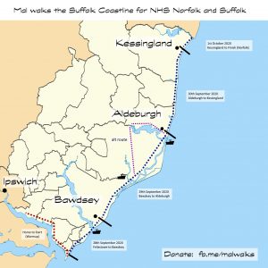
In my latest adventure I am taking on a charity walk which I devised for myself. I am walking the entire length of the Suffolk Coastline which is approx 100km.

http://fb.me/malwalks

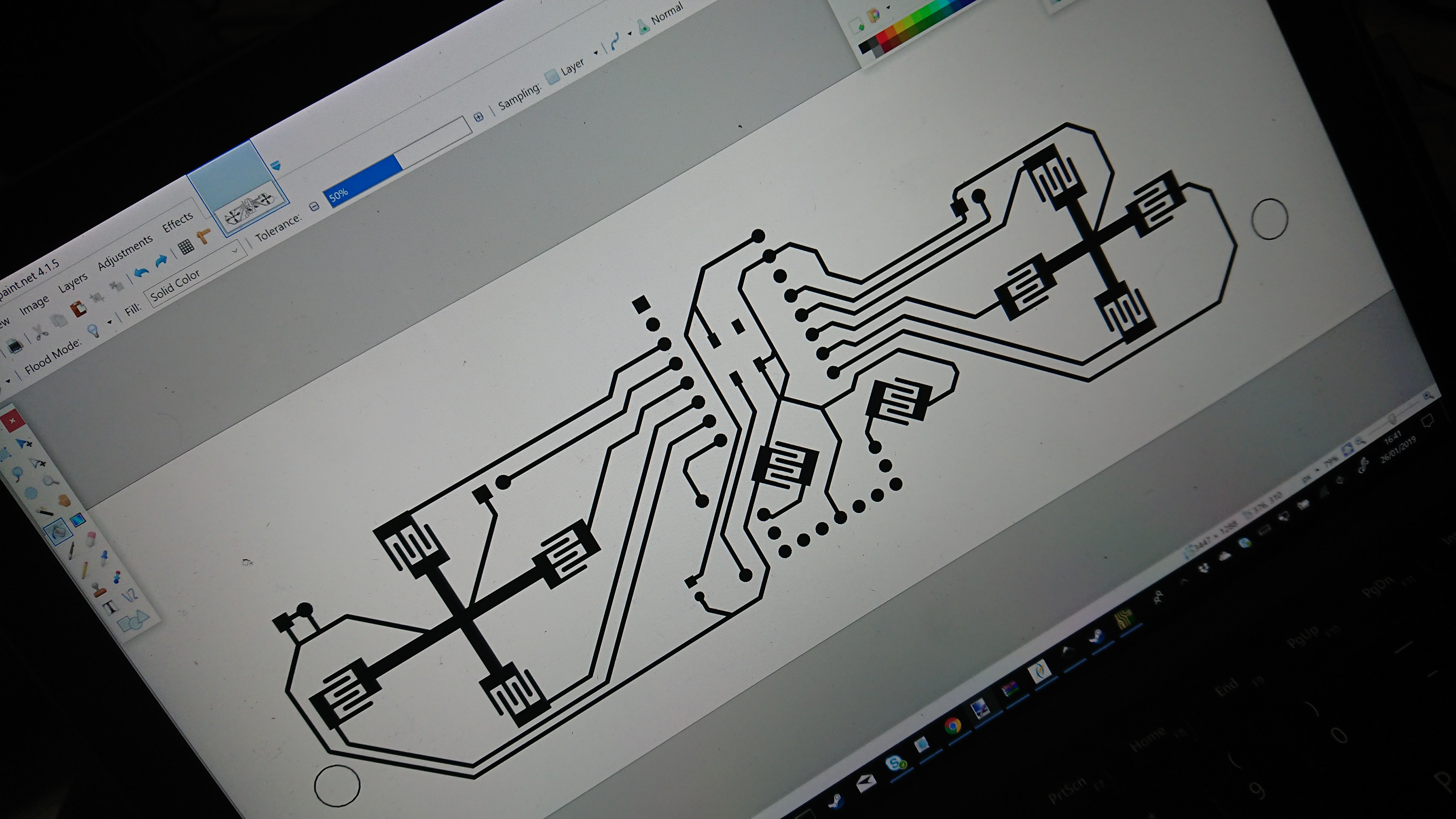
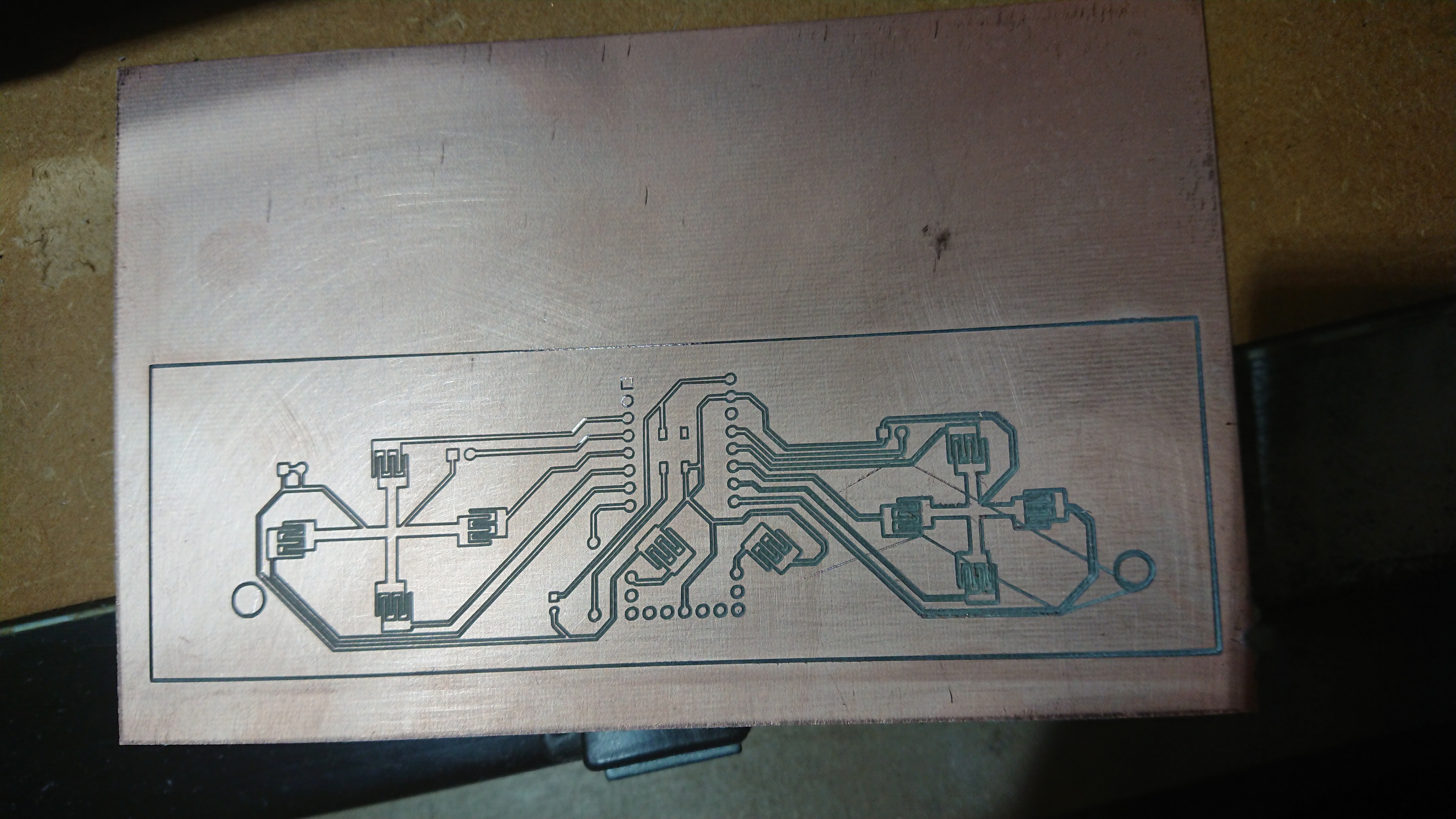
The walk itself looks a bit like this

To support my walk I have OS Maps using Viewranger for Android, the Ordnance Survey App itself and some paper maps, but as an absolute backup I took on a small electronics project to repurpose a development board into a GPS.

Objectives

#1 Display the British National Grid reference from GPS location

#2 Display my location on a map image of some sort


Board selection

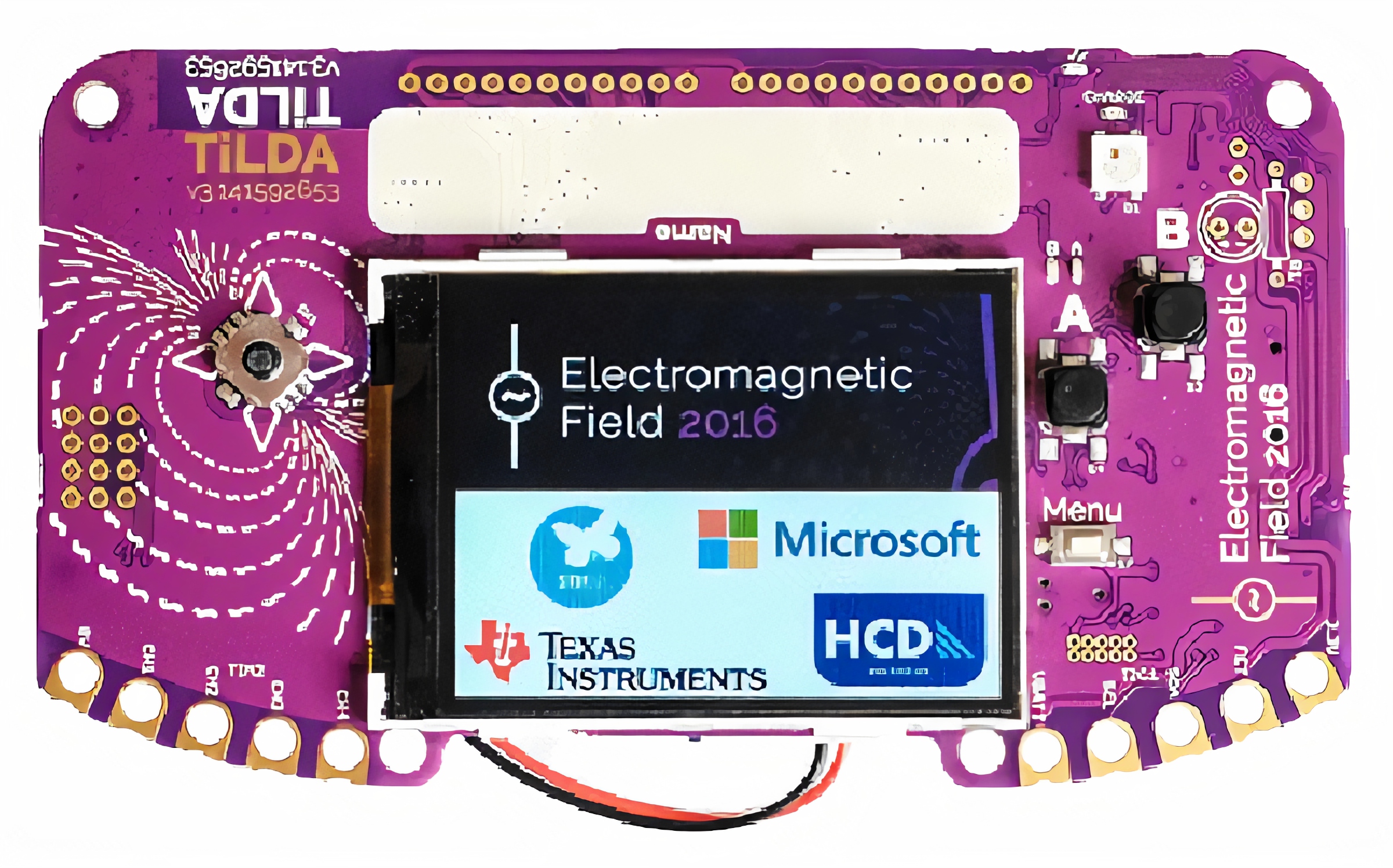
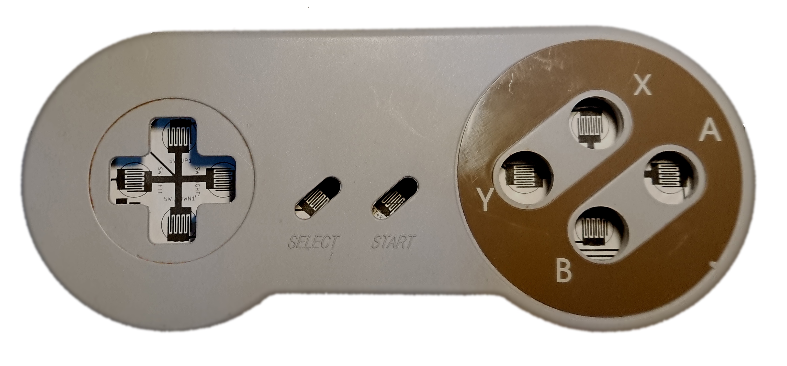
I started with what I had lying around, it needed a UART, SD card slot and a screen. So I found my EMF Camp Badge (MK3) from 2016.

SD Card Slot on the back

UART pins exposed across the top

320 x 240 colour display

D Pad and Buttons


Boot from SD card

I copied across the main scripts from the Mk3 Badge master zip file and ensured it was loading the boot and main scripts from the card, this was very easy.


WGS84 to British National Grid

Firstly I decided I should sort out converting the decimal WGS84 to BNG. I found some C code on a forum which I tested on an Arduino, then converted it to python and modified it to produce the BNG in the format i.e “TM123456”


#definitions for geometric conversions
deg2rad = 0.017453292519943295 #(PI / 180)
rad2deg = 57.29577951308232087 #(180/ PI)
a = 6377563.396 # OSGB semi-major axis
bb = 6356256.91 # OSGB semi-minor axis
e0 = 400000 # OSGB easting of false origin
n0 = -100000 # OSGB northing of false origin
f0 = 0.9996012717 # OSGB scale factor on central meridian
e2 = 0.0066705397616 # OSGB eccentricity squared
lam0 = -0.034906585039886591 # OSGB false east
phi0 = 0.85521133347722145 # OSGB false north
af0 = 6375020.48098897069 #(a * f0)
bf0 = 6353722.49048791244 #(b * f0)
n = 0.0016732202503250876 #(af0 - bf0) / (af0 + bf0)
WGS84_AXIS = 6378137 # a
WGS84_ECCENTRIC = 0.00669438037928458 #e
OSGB_AXIS = 6377563.396 #a2
OSGB_ECCENTRIC = 0.0066705397616 #e2
_xp = -446.448 #OSGB/Airy datums/parameters
_yp = 125.157
_zp = -542.06
xrot = -0.000000728190149026 #_xr -0.1502 (_xr / 3600) * deg2rad
yrot = -0.000001197489792340 #_yr -0.247 (_yr / 3600) * deg2rad
zrot = -0.000004082616008623 #_zr -0.8421 (_zr / 3600) * deg2rad
_sf = 0.0000204894 # s=20.4894 ppm
LETTERS = [ [ "V", "W", "X", "Y", "Z" ], [ "Q", "R", "S", "T", "U" ], [ "L", "M", "N", "O", "P" ], [ "F", "G", "H", "J", "K" ], [ "A", "B", "C", "D", "E" ] ]


def right(s, amount):
return s[-amount:]
def left(s, amount):
return s[:amount]


def Marc(phi):
return bf0 * (((1 + n + ((5 / 4) * (n * n)) + ((5 / 4) * (n * n * n))) * (phi - phi0)) - (((3 * n) + (3 * (n * n)) + ((21 / 8) * (n * n * n))) * (sin(phi - phi0)) * (cos(phi + phi0))) + ((((15 / 8) * (n * n)) + ((15 / 8) * (n * n * n))) * (sin(2 * (phi - phi0))) * (cos(2 * (phi + phi0)))) - (((35 / 24) * (n * n * n)) * (sin(3 * (phi - phi0))) * (cos(3 * (phi + phi0)))))


def LLtoNE(latConv,lonConv,heightConv):
latConv*= deg2rad # convert latitude to radians
lonConv*= deg2rad # convert longitude to radians
v = WGS84_AXIS / (sqrt(1 - (WGS84_ECCENTRIC *(sin(latConv) * sin(latConv)))))
x = (v + heightConv) * cos(latConv) * cos(lonConv)
y = (v + heightConv) * cos(latConv) * sin(lonConv)
z = ((1 - WGS84_ECCENTRIC) * v + heightConv) * sin(latConv)
# transform cartesian
hx = x + (x * _sf) - (y * zrot) + (z * yrot) + _xp
hy = (x * zrot) + y + (y * _sf) - (z * xrot) + _yp
hz = (-1 * x * yrot) + (y * xrot) + z + (z * _sf) + _zp
# Convert back to lat, lon
lonConv = atan(hy / hx)
p = sqrt((hx * hx) + (hy * hy))
latConv = atan(hz / (p * (1 - OSGB_ECCENTRIC)))
v = OSGB_AXIS / (sqrt(1 - OSGB_ECCENTRIC * (sin(latConv) * sin(latConv))))
errvalue = 1.0
lat1 = 0
while errvalue > (1/1024):
lat1 = atan((hz + OSGB_ECCENTRIC * v * sin(latConv)) / p)
errvalue = abs(lat1 - latConv)
latConv = lat1
output_airy_elevation = p / cos(latConv) - v
# Convert OSGB36/Airy into OS grid eastings and northings
# easting
slat2 = sin(latConv) * sin(latConv)
nu = af0 / (sqrt(1 - (e2 * (slat2))))
rho = (nu * (1 - e2)) / (1 - (e2 * slat2))
eta2 = (nu / rho) - 1
pp = lonConv - lam0
IV = nu * cos(latConv)
clat3 = pow(cos(latConv), 3)
tlat2 = tan(latConv) * tan(latConv)
V = (nu / 6) * clat3 * ((nu / rho) - tlat2)
clat5 = pow(cos(latConv), 5)
tlat4 = pow(tan(latConv), 4)
VI = (nu / 120) * clat5 * ((5 - (18 * tlat2)) + tlat4 + (14 * eta2) - (58 * tlat2 * eta2))
output_os_eastings = e0 + (pp * IV) + (pow(pp, 3) * V) + (pow(pp, 5) * VI)
# northing
M = Marc(latConv)
I = M + (n0)
II = (nu / 2) * sin(latConv) * cos(latConv)
III = ((nu / 24) * sin(latConv) * pow(cos(latConv), 3)) * (5 - pow(tan(latConv), 2) + (9 * eta2))
IIIA = ((nu / 720) * sin(latConv) * clat5) * (61 - (58 * tlat2) + tlat4)
output_os_northings = I + ((pp * pp) * II) + (pow(pp, 4) * III) + (pow(pp, 6) * IIIA)
#letters
xf = output_os_eastings/500000;
yf = output_os_northings/500000;
s1x = (trunc(xf)) + 2;
s1y = (trunc(yf)) + 1;
s1 = LETTERS[s1y][s1x];
xf = (output_os_eastings % 500000)/100000;
yf = (output_os_northings % 500000)/100000;
s2x = trunc(xf);
s2y = trunc(yf);
s2 = LETTERS[s2y][s2x];
output_grid = s1 + s2
output_east = right(str(trunc(output_os_eastings)), 5)
output_north = right(str(trunc(output_os_northings)), 5)
output = [output_os_eastings, output_os_northings, output_airy_elevation, output_grid, output_east, output_north,s1x,s1y,s2x,s2y]
return output

Connect a GPS

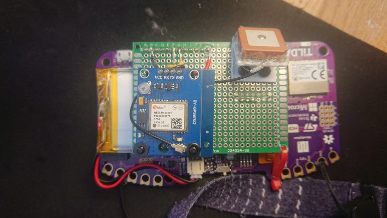
The next step was to put a real GPS on it and get a location back. I selected a ublox Neo-6M and mounted it (shoddily) to the back of the Badge. It could have been much more compact, I won’t risk changing it now with 1 week to go to the start of the walk (28/09/20). I 3d printed an antenna mount and glued the antenna to it. It is connected with some header pins, so I could change it in a future revision. I wish all these boards layed out the UART or SPI or I2C pins in the space order and spacing, because it is a bit of a pain.

I tried the default large ceramic active antenna, a small ceramic active antenna, a small passive lcb antenna, and a wifi antenna (cut down to 1/8th wavelength) and found that while they all worked, this large ceramic antenna seemed to perform the best in real world test.

Interfacing GPS

I found a python module online micropyGPS here https://github.com/inmcm/micropyGPS

I quickly ran out of RAM and had to take an axe to the module code and chop out stuff I wasn’t using (speed calculations & logging)

It was simple to interface the module, in the main loop it just reads characters from the UART and passes them into the module and prints them to the serial port (for testing the GPS)


my_gps = MicropyGPS()
my_gps.coord_format = "dd"
uart = UART(3, 9600, read_buf_len=1000)


while uart.any():
----ledg.on()
----char = chr(uart.readchar())
----my_gps.update(char) # Note the conversion to to chr, UART outputs ints normally
----output += char
----if (char == "\n"):
--------print (output, end = '')
--------output = ""
----ledg.off()

The location can be grabbed and converted


lat = float(my_gps.latitude[0])
long = float(my_gps.longitude[0])
location = LLtoNE(lat,long,0)

Interfacing the screen

Working with the screen is simple with ugfx, here are some examples I used


ugfx.area(0,0,140,20,ugfx.WHITE)
ugfx.text(3, 0, str(location[3] + "_" + location[4] + "_" + location[5]) + " ", ugfx.BLACK)

Loading maps

To meet objective #2, I loaded the SD cards with some gif files that represent each 1km square for example TM1941.gif, TM2041.gif etc and loaded up the current tile.


ugfx.display_image(0, 0, strimage)
ugfx.display_image(240, 0, strimage_east)

strimage is the path to the current 1km tile, and strimage_east, is the tile to the east of that. this is because the tiles are 240×240 pixels, but the screen is 320 wide, so I get 80 pixels of the next tile displayed as well to use the screen real estate.
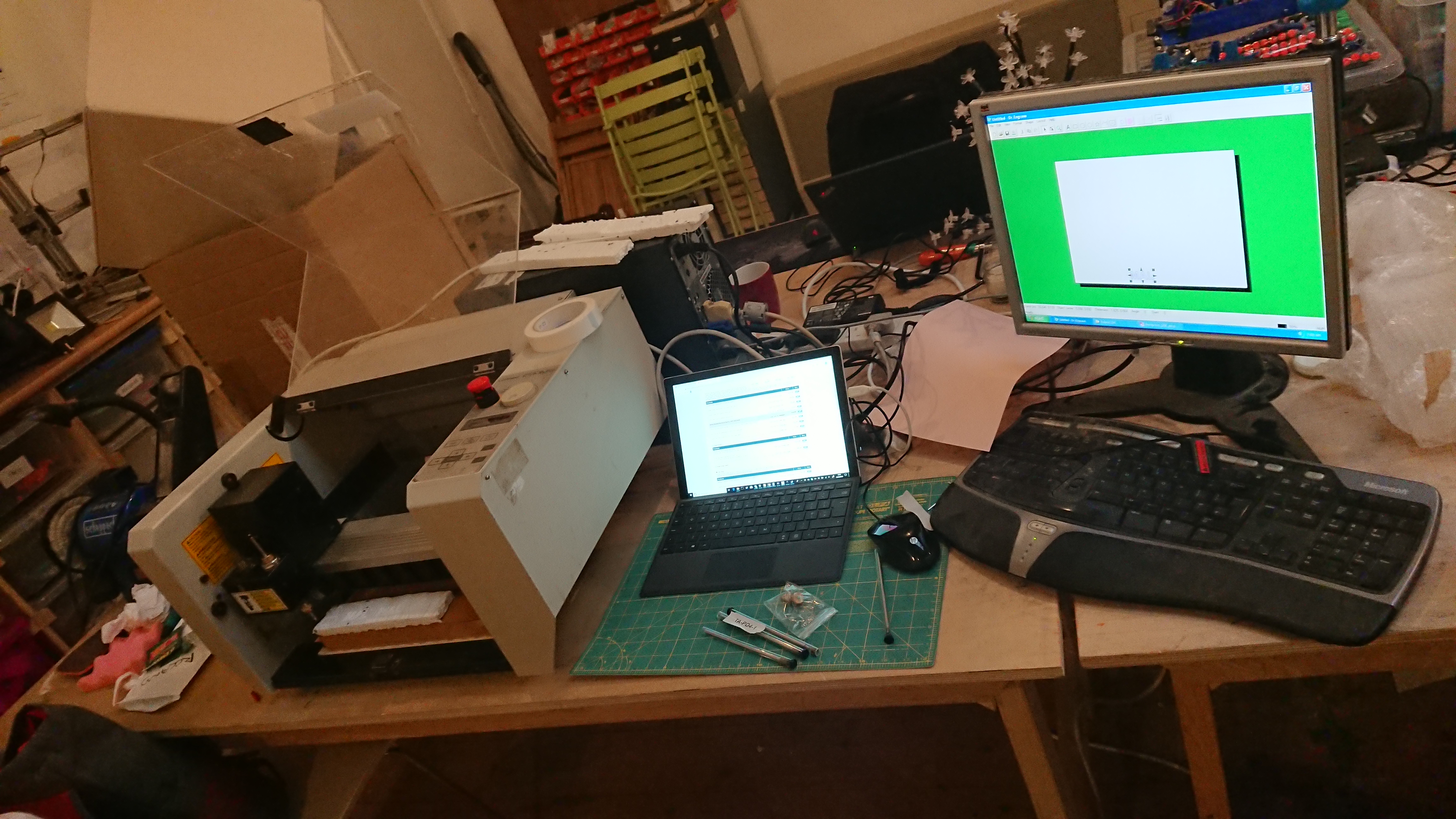
Final result

Once I put some logic around all the examples above to take input from the buttons and added code to draw the battery voltage and cursor. Here is a video demo.

These maps bear some similarity to the Ordnance Surveys maps, but they are of course not, these few maps tiles shown here were digitally recreated by myself using mspaint 😀

Consumer Advice #1 – Samsung C27HG70 setup for Win10 gaming

Hey. In this quick blog I outline the settings I used to make the most out of my new monitor. It took a while to get right, but once its right the C27HG70 makes for an all round decent display.

About

Some key technical details about the display

  • Aspect Ratio 16:9
  • Display Type QLED monitor / TFT active matrix
  • Features Black eQualizer, 92% Adobe RGB colour gamut, FPS Mode, Flicker Free technology, RTS Mode, Eco Saving Plus, Eye Saver Mode, Low Input Lag, Quantum Dot Technology, 125% sRGB colour gamut, Super Arena Gaming UX, 88% (NTSC 1976) colour gamut, HDR (high dynamic range), Screen Size Optimizer, Refresh Rate Optimizer, Game Color Mode, Custom Key
  • Energy Class Class D
  • Energy Consumption per Year 91 kWh
  • Power Consumption (On mode) 62 W
  • Diagonal Size 27″
  • Viewable Size 26.9″
  • Curved Screen Yes (1800R)
  • Adaptive-Sync Technology AMD FreeSync
  • Built-in Devices USB 3.0 hub
  • Panel Type VA
  • Native Resolution Ultra WQHD 2560 x 1440 at 144 Hz
  • Brightness 600 cd/m²
  • Contrast Ratio 3000:1
  • Colour Support 1.07 billion colours
  • Response Time 1 ms
  • Horizontal Viewing Angle 178
  • Vertical Viewing Angle 178
  • Backlight Technology LED backlight
  • Colour Matte dark blue grey
  • Dimensions (WxDxH) 62.48 cm x 39.07 cm x 55.67 cm – with stand
  • Weight 6.3 kg

Setup

A setup for flexible gaming and casual desktop use.

  • Windows 10 Pro
  • Intel i7 8086K
  • nVidia RTX2080 Super

Displayport cable

The first thing I needed to do to set this up is take the Samsung Display Port cable that came with the display, open a window and throw it out towards the garbage. It was useless, the screen would continually flicker horribly. Even a Belkin cable I bought from Poundland 8 years ago did a better job !

I recommend getting a Displayport certified cable https://www.displayport.org/product-category/cables-adaptors/ or even raiding the local poundland it seems.

Resolution and colour depth

Set the native resolution for the screen. 2560 x 1440 @ 144Hz and enable 10 bits per channel colour depth and full dynamic range.

Adaptive Sync

Don’t forget to turn on nVidia Gsync

Colour profile

It is useful to tell your operating system what colours the display can output. Samsung provide a .icc profile file for this.

Screen setup

Use the on-screen controls (little d-pad button to the rear right of the screen)

I set it as the following :

I found the contrast and sharpness to be particularly important to reduce “VA glow”. For a few weeks I would notice that in the darker parts of some games, when the screen is changing (walking forwards) some objects would emit a glowly edge. I came to found that this is known as “VA glow”. Due to the panel technology this is a common problem. Some users attributed it to the freesync technology. I was able to tune the settings to avoid the glow. Setting the sharpness below 60 really seemed to exacerbate it the problem!

HDR

Don’t be tempted to turn HDR on for the desktop for general use, it seems to reduce the tonal depth of the desktop and give it a high brightness, low contrast glimmer look. However, if you consuming HDR content full-screen from either Youtube, VLC or a Bluray player, then do turn it on for that session, it really does make HDR content look impressive. Not something I can really show you here !

Game tuning

Some games let you set the max FPS the game will run at, this will help reduce heat from the graphics cards for games that would usually run at the max refresh rate of the display (144fps). In Witcher 3, I have to set it to unlimited as it only has an option for 30 or 60 (probably being an older game).

With the adaptive sync technology enabled, I can get 90 fps in Witcher 3 and it looks really smooth, again I can’t show you but it is impressive looking.

Hope this has been helpful.


Coronavirus Update

In line with the latest government advice we are cancelling our regular meetings, effective immediately. As the situation changes we will keep you updated. If you need access to the space to collect personal items, tools, projects etc please let us know and we will arrange a date and time.

Adventure #6 – CNC PCB

In this adventure I attempt to get the Roland Camm-2 2300/A CNC machine to mill a PCB into some copper board. This is what the temporary setup looks like. I have the CNC machine, laptop, and an old XP machine.

We have procured a set of tools for the Roland specifically for milling and drilling PCBs. I started by testing on some polystyrene (as in the above), which seemed to go OK so I thought I would move to my PCB project. I took the Copper layer and converted it to a bitmap such that Dr Engrave can import it. It was at this point I knew I was in too deep and it could only go wrong.

I stuck down the copper board with some double sided tape. After some fiddling with the tool settings and trying to position the tool itself correctly on the Z-axis, I pressed the “print” button and closed my eyes! There was not too much I could do at this point, it was either going to start neatly cutting out the tracks or crash into the end and start eating itself. My polystyrene test did not fill me with any more confidence, but my hand was positioned over the emergency stop button.

After a few minutes of whirring and buzzing, I was presented with this (below)  🙁

It’s not what I expected, but for my first attempt I suppose it could have been worse. Let me take you through it.

  • Its not cut evenly at all, there must be some severe levelling problems with the bed and/or the material
  • The tracks are very thin and pretty wobbly looking
  • The tool hasn’t lifted off properly and has wiped a skid mark across it
  • The pads are very small and wont take drilling without disappearing entirely
  • The “toothed” button pads are a mess, one is just a gaping hole

Next steps are to:

  • Get a fatter tool to mill the wooden bed flat
  • Make a jig and/or test sticking down the copper much flatter
  • Redesign the layout with fatter tracks that are father apart
  • Test cutting out the edge cuts
  • Test drilling to through holes
  • Try again

Thats all for today, I will keep you updated on the progress.

Adventure #4 – SNES Controller Distraction

Instead of trying to finish off one project at a time, I got distracted with dissecting a SNES controller. In this brief project I am converting it into an XINPUT compatible controller by way of a custom PCB and Teensy LC.

Firstly I cracked open the case a got a good look at its innards. Its made up of the PCB, buttons and rubber parts with conductive pads.

The challenge is to fit a Teensy-LC into the case, in roughly the same size PCB. As with my other XINPUT Teensy project, each button needs wiring to GND and a GPIO. I decided to upgrade the controller a bit by adding a Neopixel.

The schematic shown below uses:

1 Teensy-LC component for Kicad
10 push switches for the top buttons
pin headers for shoulder buttons and grounds
1 x Neopixel plus is resistor and capacitor

The layout took a few iterations and much measuring before finalising it. My first challenge was to create a footprint for the button contacts.

In order to make pads of custom shape, I needed to upgrade to Kicad 5. To make the custom shape, one had to create a pad, then draw the rest of the irregular shapes using “graphic lines”. Once done, select them all, RMB and use “Create Pad from selected shapes”. The gaps between pads are 0.5mm.

I found a 3d render of a teensy-lc and modified it a bit to suit the project. This enabled me to visualise the fit. The teensy reset button made need poking out of the back of the case (or removing)

click to embiggen

The code is this time based on MSF Flightstick, which is a very easy way to make an XINPUT compatible device. I should really have done something cool like put an accelerometer in it. I think the next one might be wireless. I have found some sweet looking 433MHz modules “HC-12”, which I will mess around with in another blog. Here is it printed out and placed in the case, if only I could laser print copper.. It isn’t as badly aligned as it looks, that is just the parallax effect. It is that filthy though!

As I can get away with not plating the through holes I am tempted to use the recently renovated CNC milling machine in the makerspace to make the board. OSHPark nicely gives me the various layers, top and bottom copper, soldier mask and silk screen and drills. I guess I would have to figure out how to generate those layers myself from Kicad and make sure the dodgy Roland software running on Windows XP can understand it. I will also need to research if I can add soldier mask myself and how I can mask the pads. Yet another blog I think! I will do a seperate blog on my attempts to resurrect the Roland PNC-2300A!

Once I have produced a board and tested it, I will link to that blog from here 🙂 That is all, until our next adventure.


Coderus Sponsorship

Software design engineering company Coderus, based at Martlesham, has announced a sponsorship deal with the Ipswich Makerspace which will see staff from the firm get involved with the community tech and making hub. In return for their support, employees from Coderus will be invited to make use of the equipment and facilities available at the Makerspace’s Dove Street facility.

Coderus has a long-standing commitment to engaging with its community and feels that it shares the same core values and passion about technology as the Ipswich Makerspace. Pillar drills, laser cutters, CNC machine and 3D printers are some of the equipment that the members can use among a wide variety of tools for any type of craft or project. Tech enthusiasts will also have the opportunity to work on either individual or group projects, with free soldering consultation as an option. Each Coderus member will have the opportunity to visit the Makerspace and work on projects, as well as attending the regular meetups and in-house projects.

“From modern hardware to traditional crafts, Ipswich Makerspace fits perfectly the interests of our team”, said Mark Thomas, Director of Coderus. “It has been really nice seeing some of the guys using the laser cutter and the 3D printers for their own projects already. Stephen Chalkley has welcomed us all.”

Stephen Chalkley of the Ipswich Makerspace said: “We’ve grown from a small group meeting in a draughty church hall to having our own building in just a few years. Our members have an enormous range of experience and skills and they are very generous about sharing them. Being sponsored by Coderus is a great validation of our efforts and we’re looking forward to working with them.”

“There’s a great synergy between Coderus and the Ipswich Makerspace as they both provide fertile ground for innovative ideas.”

Adventure #3 – If I could chuck wood….

Merry Christmas adventurers. In this adventure I am building the frame for my arcade machine. It is built of Wickes’ finest 12mm MDF. It is held together with pine and prayer. My brother and I used the tablesaw to cut the front, sides and back. In this image it is waiting for its face.

I have stripped down an LCD monitor and mounted it in the frame.

After getting the frame together and standing in front of it, it only really seemed big enough for 2 players. I have tested mounting the joysticks.

Kindly Ipswich Makerspace’s own superhero Adam helped laser out the screen surround on “Helios” the big laser.

It me

Outstanding jobs

  • Build replacement button PCB to control the LCD
  • Procure PC parts and mounting system
  • Install IEC C14 connector and power button
  • Vinyl wrap
  • Finish and polish the turd game in Unity
  • Unleash it on people

Look out for my other adventures where I go off down rabbits holes, such as:

  • Write a new game! and build its artwork
  • Convert a SNES controller to XINPUT compatible
  • Build my own gaming mechanical keyboard
  • Hack a Boilermate 200 PCB into a “Smart” Boiler
  • Macro photography
  • Learning Finnish and the Piano
  • Something to do with my day job, I forget what it is now, probably Internet or phones or something.