Adventure #5 – Boilermate 2000 Hack
OK so I’m really going off on a tangent now… I have decided to work out how the controller of my heating system works, and to a smart modification. This is likely pt1 of 2.
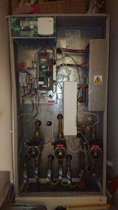
Here is the system, the wonderful Boilermate 2000.
| In the top left is the PCB that runs the various pumps and things. These have a habit of failing every year or so, so I have built up a small collection of partially failed boards. I decided to attempt to work out how they worked and see what hacks I could do to them. This board is responsible for taking an input switched live signal from an external thermostat, monitoring the hot water tank temperature, controlling the Boiler, Boiler Pump, DHW pump and Central Heating pump.
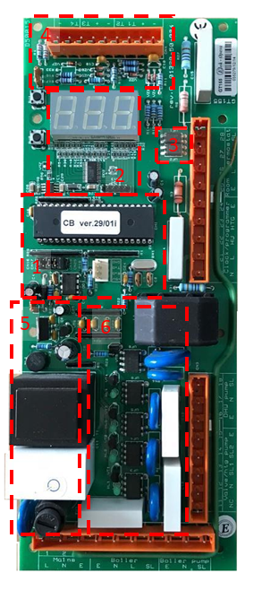
This is a GT155 with the updated LED display driver. This one suffered from not being able to turn the DHW pump fully on, I think a triac has failed, but I don’t really know how to test it and to watch me desolder anything is like watching a lion pull the carcass of an antelope out of the passenger door of a nissan micra whilst balanced on a cliff top – like at the end of the Italian job. It’s dangerous, messy and probably doesn’t end well for anyone. Let’s talk through what we have here. |
Let’s take an in-depth look at some of these components.
Main CPU
The main CPU is a AT89C55 8-bit microcontroller with 20K of flash with 32 I/O lines. It is in PDIP configuration and socketed for easy extraction (he says instantly bending 4 of the pins).
X5045P
I misunderstood what this was a first, I thought it was just an EEPROM and tried to interface with it using SPI to read its contents. After a couple of hours failing at that, I actually looked at the datasheet and followed the traces again to discover that in fact it is a CPU supervisor (with some EEPROM) and that it was just being used to keep the CPU reset if the Vcc was below Vtrig, some kind of low voltage protection mechanism.
Jumpers
These configure the programme for various Boilermate systems
- Boilermate III with jumpers in position J4
- Systemate III with jumpers in positions J3 & J4
- Systemate 2000 with jumpers in positions J1 & J4
- Electramate 2000 170/9kW and 270/9kW with jumpers in positions J2 & J4
- Boilermate 2000 the jumpers are on positions J1, J3 & J4.
This PCB will fit the units above and can be used in place of GD131 – This model also fits other products but will need the jumpers re-configuring to suit the application.


