
Last week we got lots of lovely kit from which TractorBot 2015 will be built. This week we started to put it together, albeit in a bit of a temporary way.
A few things need to be done, the big one is to run the motors up with wheels on so we can measure the stall current, this will then tell us the current the motor driver needs to handle. We have two motor drivers each handle 2 amps per channel, the drivers have two channels each so that gives us a total of 8 amps capacity. Keith is hoping that just one of the motor drivers will do, but until the test is complete we just don’t know.

3D render of hub
To test the stall current of the motors the wheels need to be attached, it is very difficult to stop a motor turning by holding the shaft. The only problem here is the the wheels we have came with a hub attachment for a 3mm diameter motor shaft, the motors however have a 6mm diameter shaft.
Keith quickly drew up a new hub attachment in AutoDesk Fusion 360 and Phil printed them out. The first version worked okay, good enough for prototyping anyway, so Keith attached them to the wheels ready for testing.
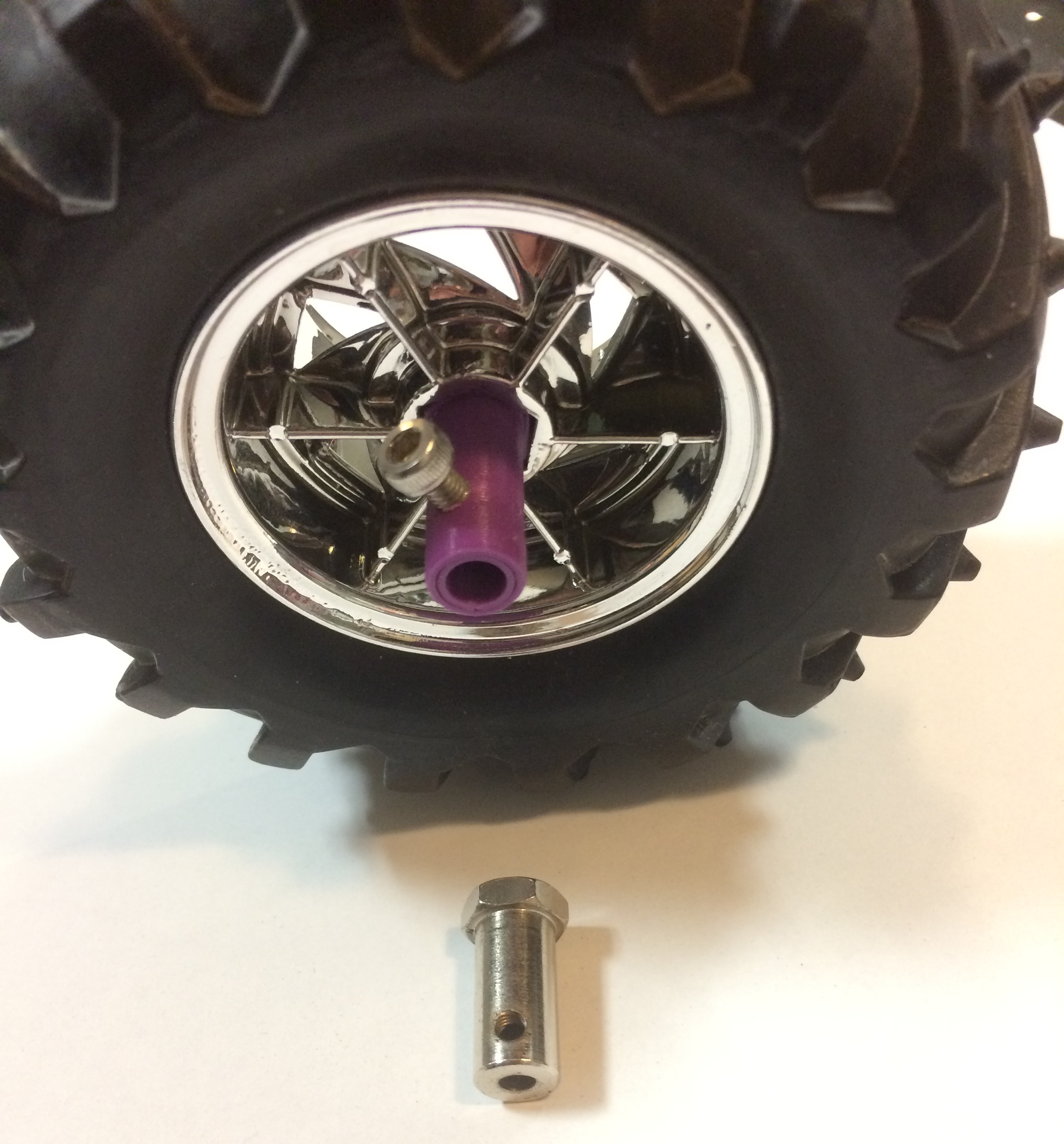
The new 3D printed hub attached to the wheel with the old one for comparison.
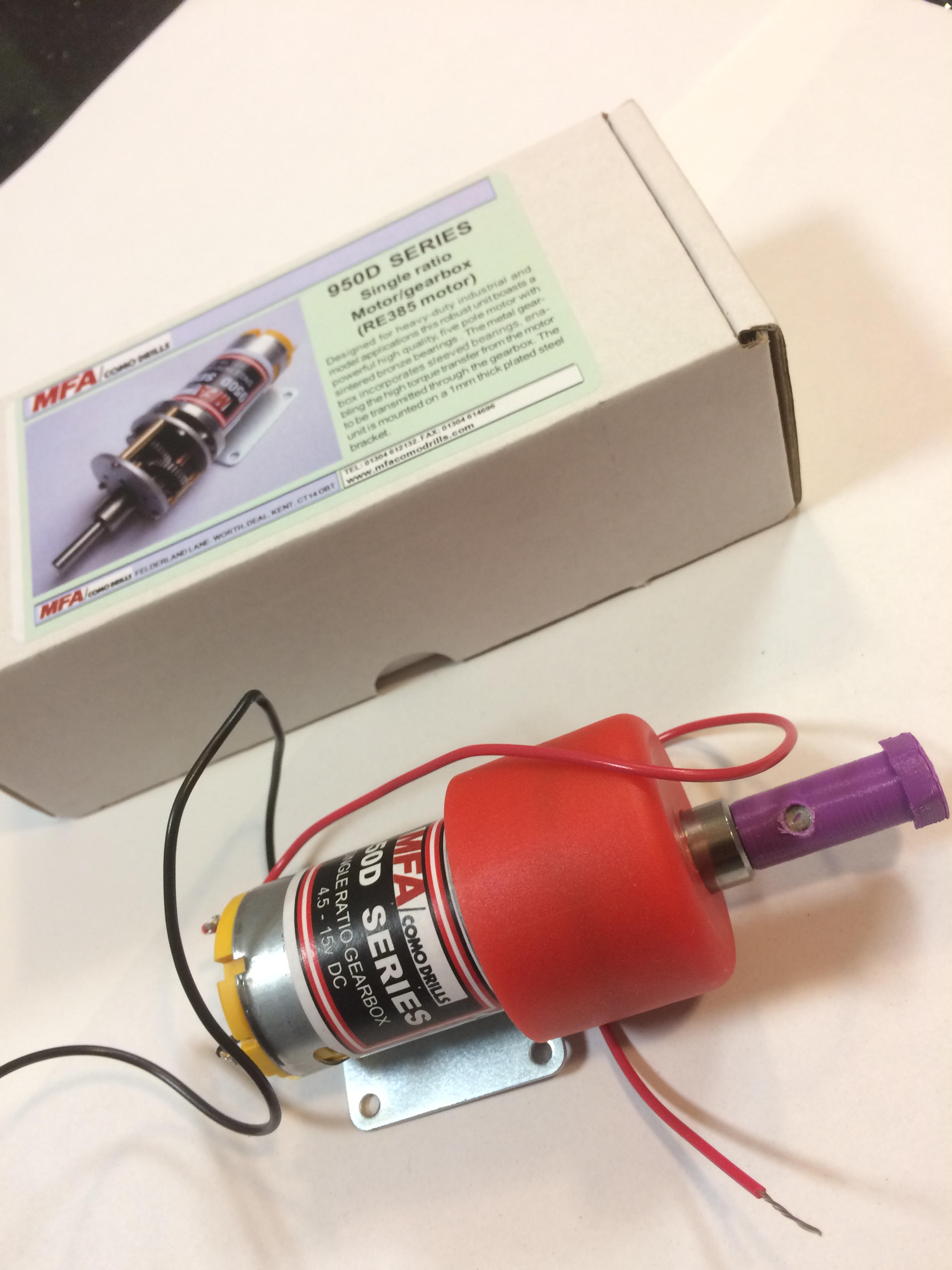
Motor with hub adapter fitted
The new hub also fits the motor like a glove, maybe a bit too well (read, Keith cannot remove it). Now the wheels are attached to the motors, Keith will dig around in his shed to find a sheet of hardboard to use as a chassis plate. The motors will be fitted and then proper testing can commence.
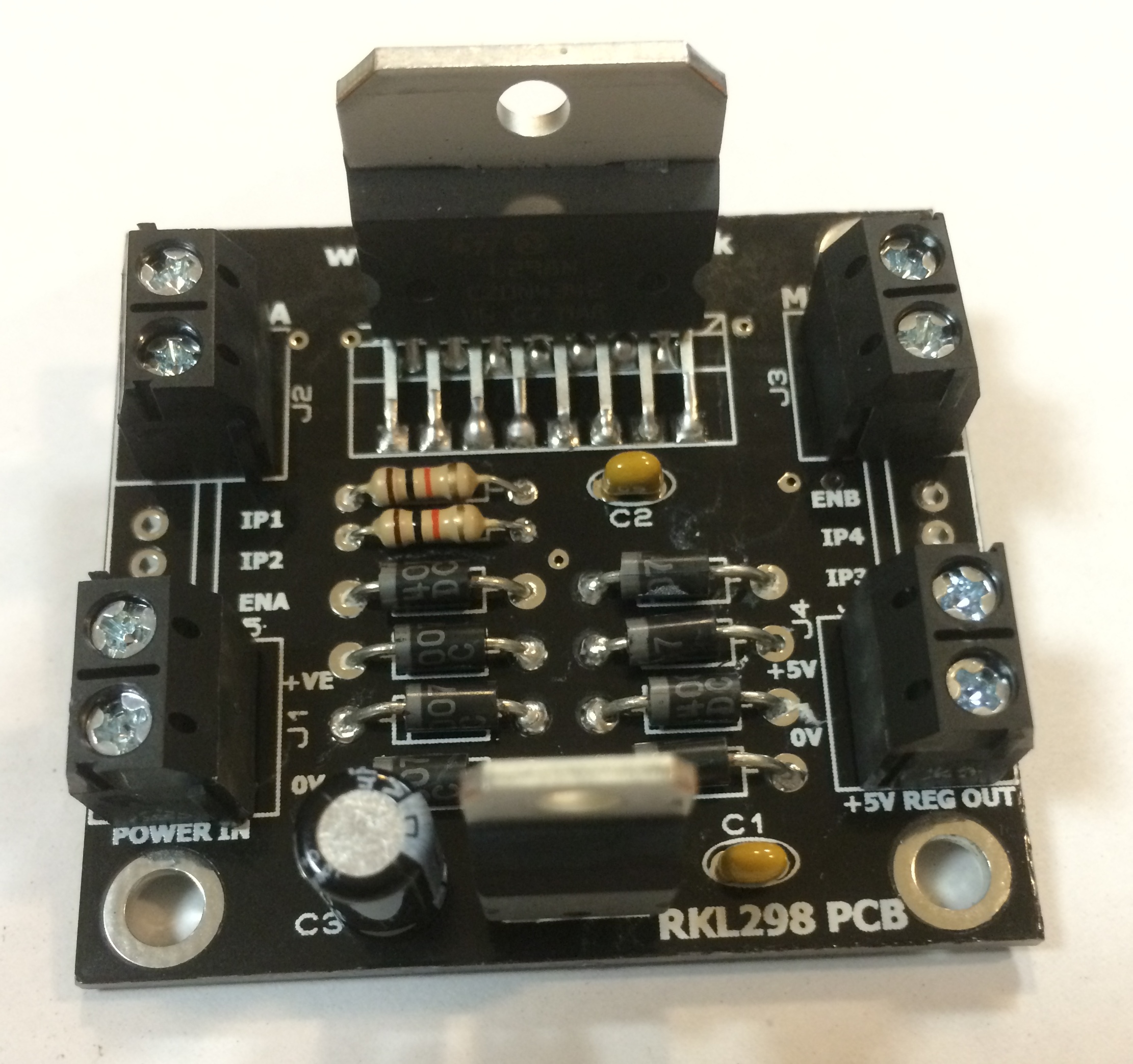
One or two of these motor drivers will be required
Further tasks required are as follows:
- Confirm the stall current for the motors, thus determine the number of motor driver to use
- Fit batteries, Raspberry Pi and motor drivers to the chassis plate
- Run some basic code, probably in Python, to check the robot moves and confirm how fast it is
- If robot is too slow running at 7.2v, try at 14.4v
- Design proper chassis plate
etc, etc………
So much to do.
Wheels and 3D printers - Ipswich Makerspace
[…] were from Rapid. With luck they had the same size hexagonal hub so they fitted straight onto the 3D printed hub converters we had made for the larger wheels. The wheels were quickly fitted and went for a test […]