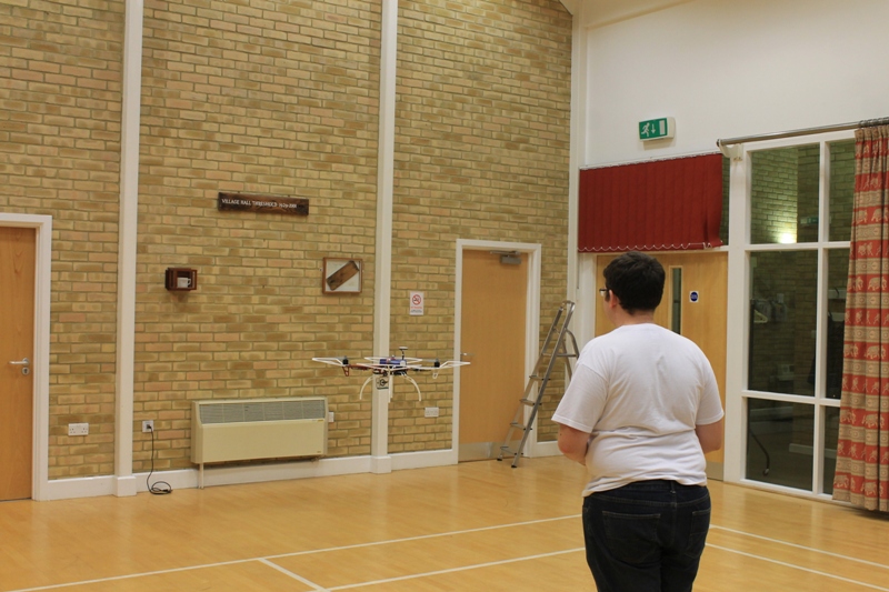
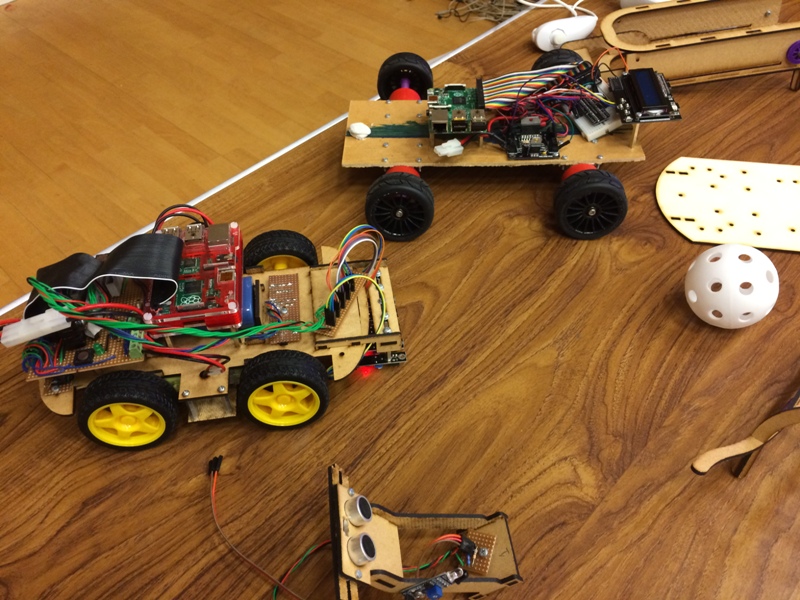
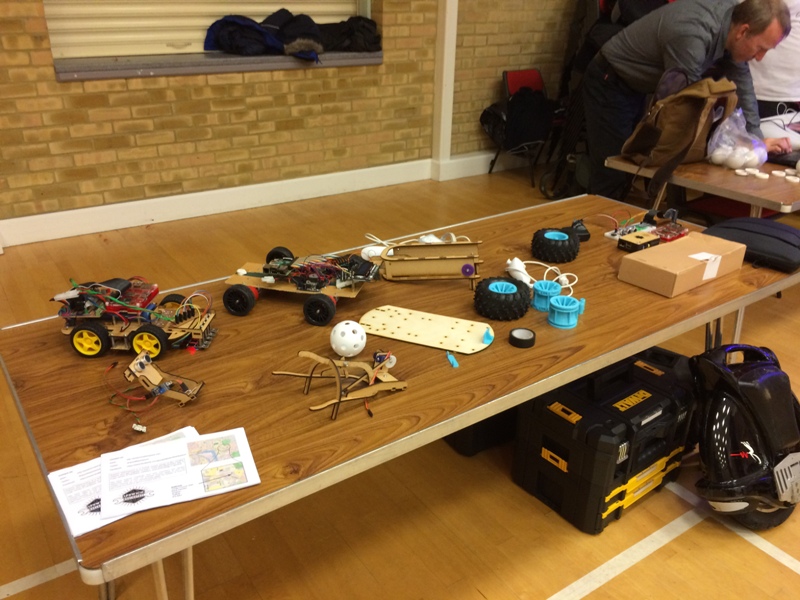
It’s been a while since the that post, largely due to getting the robot prepared. We still do not have a competition robot, we have a number of prototypes testing the code and various sensors, but the competition robot is still very virtual.
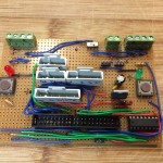
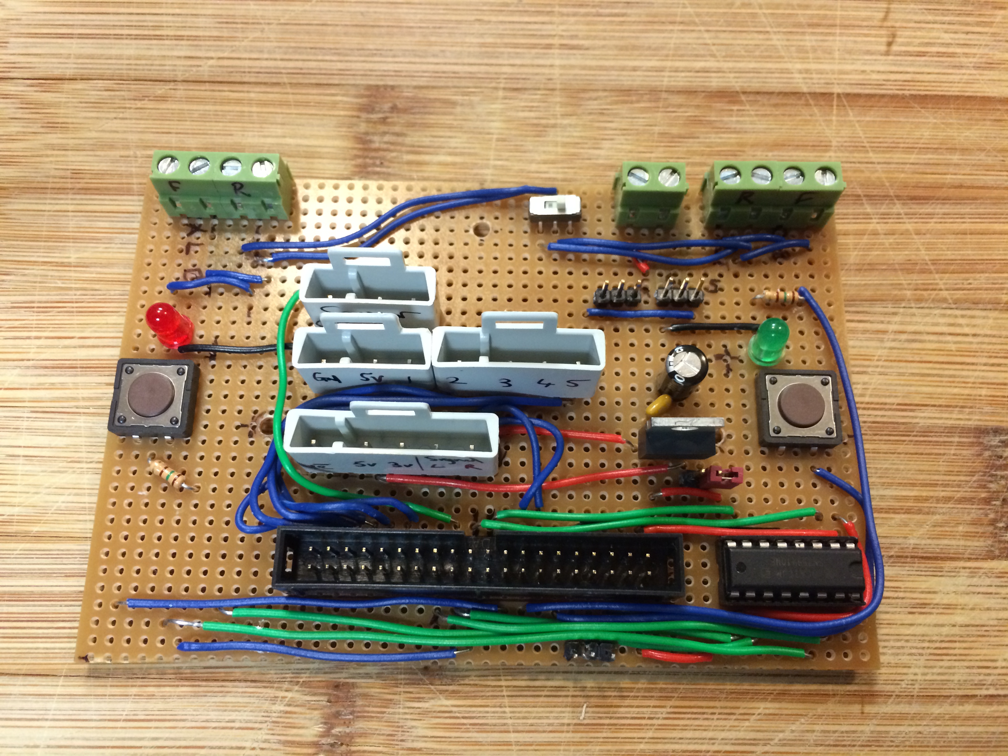
Last years interface board
The last week or so we have been working on PCB designs. Last year Keith made custom motor driver and interface boards on strip board, they worked very well but meant lots of late nights soldering. This year we were hoping to be more efficient and get purpose made PCB’s.

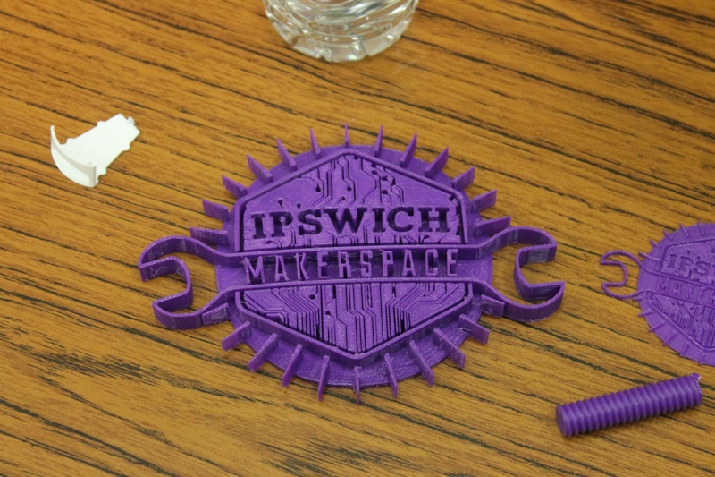
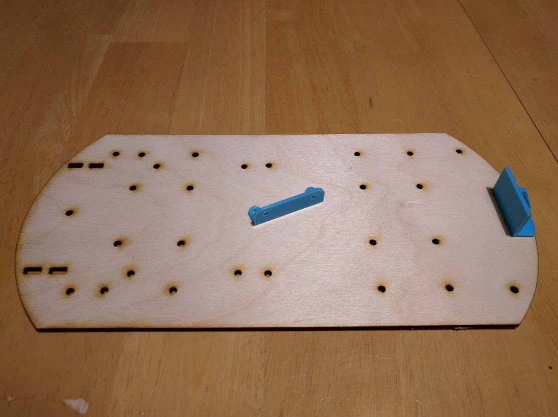
Line follower mounting PCB
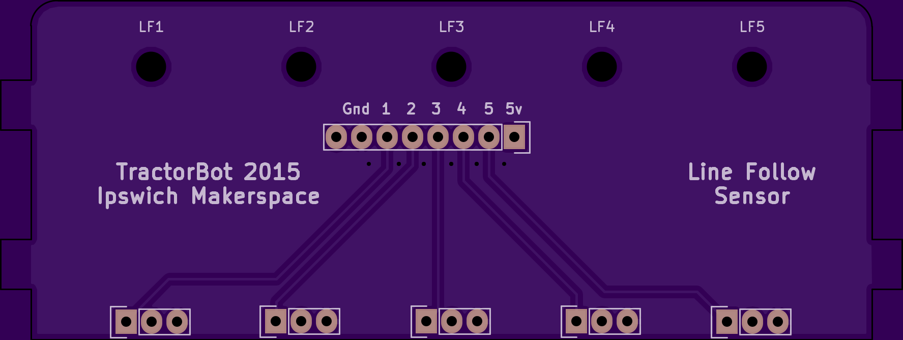
The first of which was a very simple board to interface the line follow sensors. We have five sensors each with three wires, they quickly become tangled and hard to debug if things stop working. So we have designed a PCB that the five
4Tronix line follow sensors fit to. Keith will remove the angled header pins and replace with straight header pins so they can be soldered back to back with the new PCB. The PCB will have mounting holes so the other end of the sensor can be fixed with a screw fixing. The board has tabs to allow it to slot into the laser cut chassis. On top of the board will be a pin header plug to allow us to run a common 5v, common ground and 5 signal cables to the Pi, reducing the amount of loose wires considerably.
Line sensor PCB mounted to chassis
The board was designed in Ki-Cad and sent out for pricing, we went to the usual suspects
RagWorm and
OSH Park, they were very similar prices, but for the OSH Park price you get three boards, so essentially three times cheaper (if you need three boards). The killer though was the lead time, at least two weeks or more. Keith had a hunt around a bit further and came across
Mitch Electronics, the service they offered was a bit more limited, the drill size range offered was smaller and the track widths and clearance had to be larger but there was a document explaining it all. The level of service was also more customisable, for example it is possible to select which sides of the board you want solder mask and silk screen, the only caviate being if you wank silk screen (the printed text and component outlines) you could not put it on top of solder mask. The price was also equivalent to Rag Worm and OSH Park, the clincher though was the lead time, about five working days. So the order was sent off, there were a few issues with the files Keith produced but Robin at MitchElectronics was very helpful and quickly sorted them out.

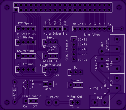
HAT style interface board
The first board is now ordered along with a second HAT style interface board which will mount directly to the top of the Pi.
If all goes well we are expecting the line follower board at any time and the interface board early next week.
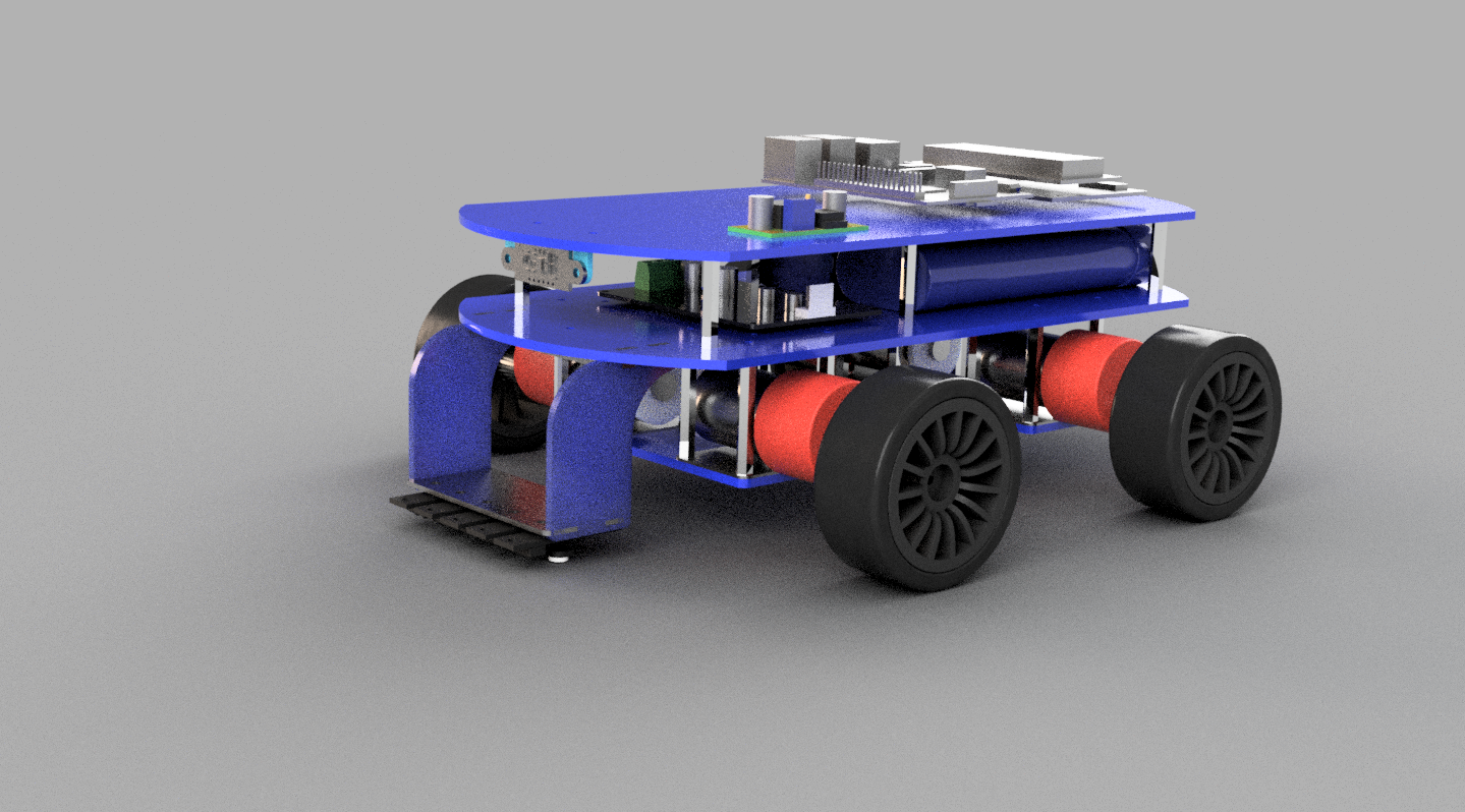
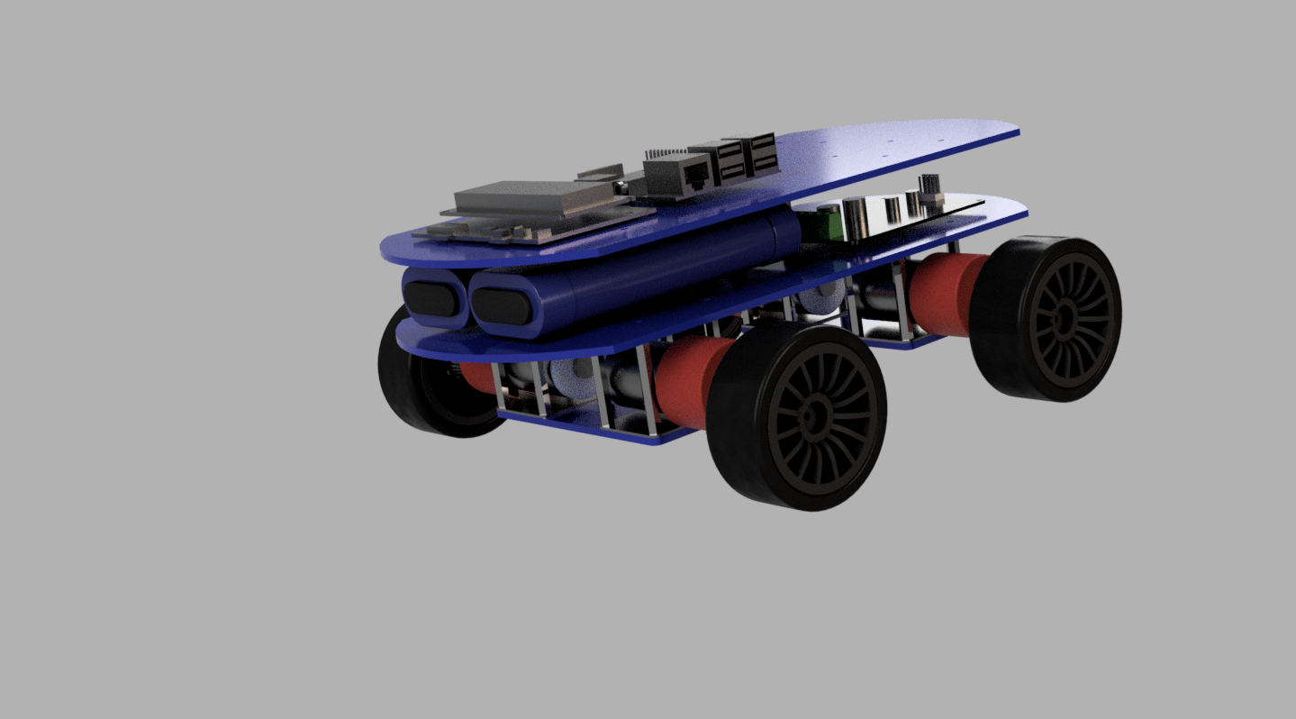
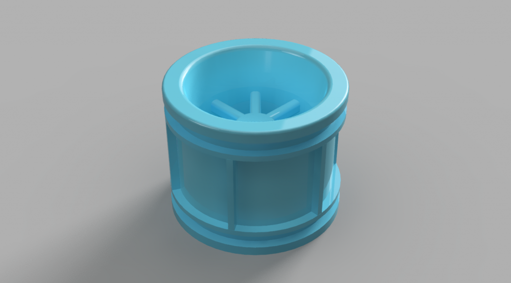
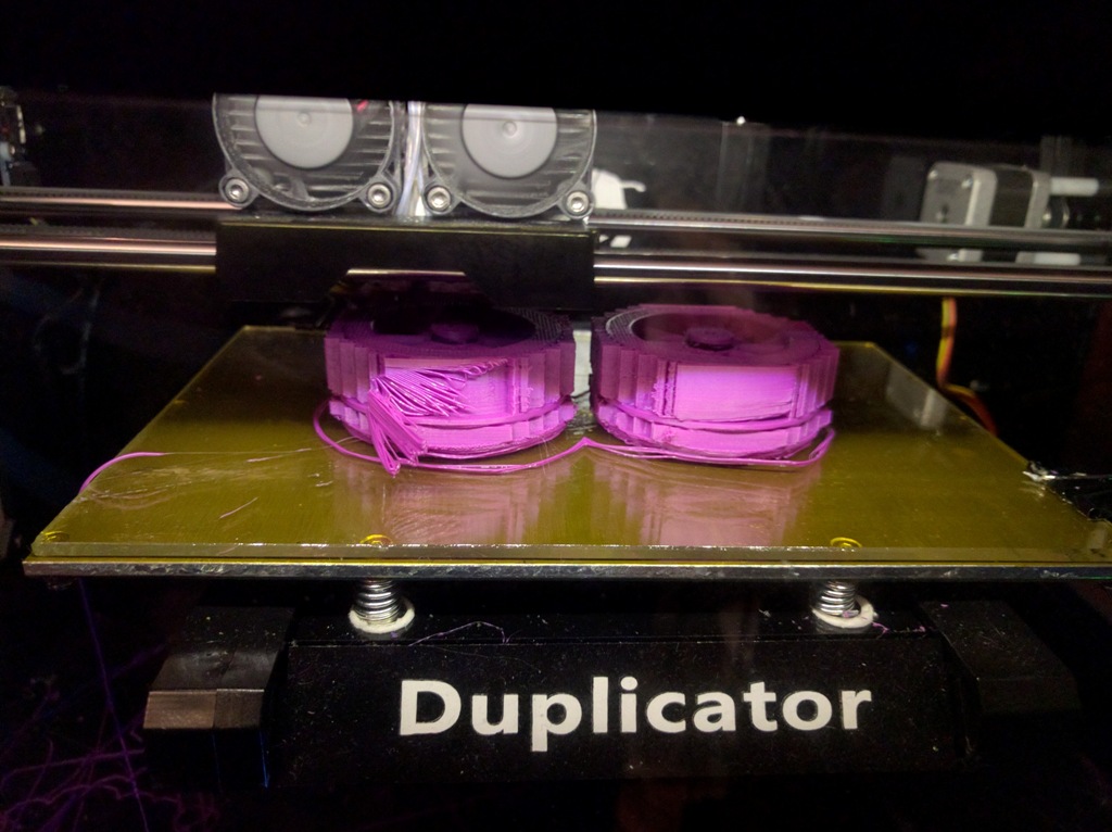
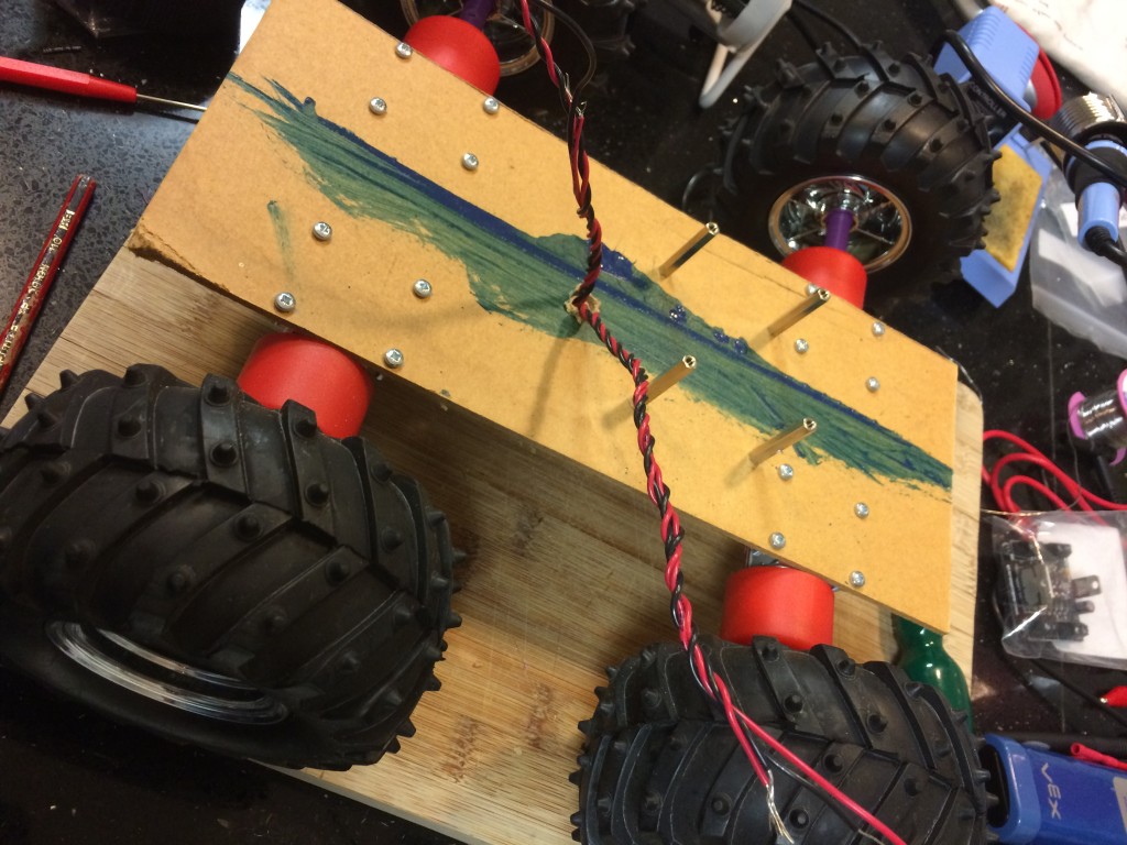
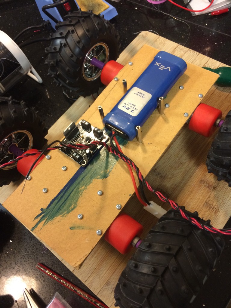
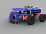
So next, probably most importantly is to make a physical robot. Over the next week Keith will be sending the laser cut and 3D print files to Phil so the robot can start to be assembled. Since this is already built in a 3D model environment it should not take too long, just a few tweaks here and there.
The main task is to convert the skittles ball launcher from 2D and get it in the 3D model so that a good fit can be ensured, oh, the trigger mechanism also needs to be designed. We still have three months to go, don’t we…
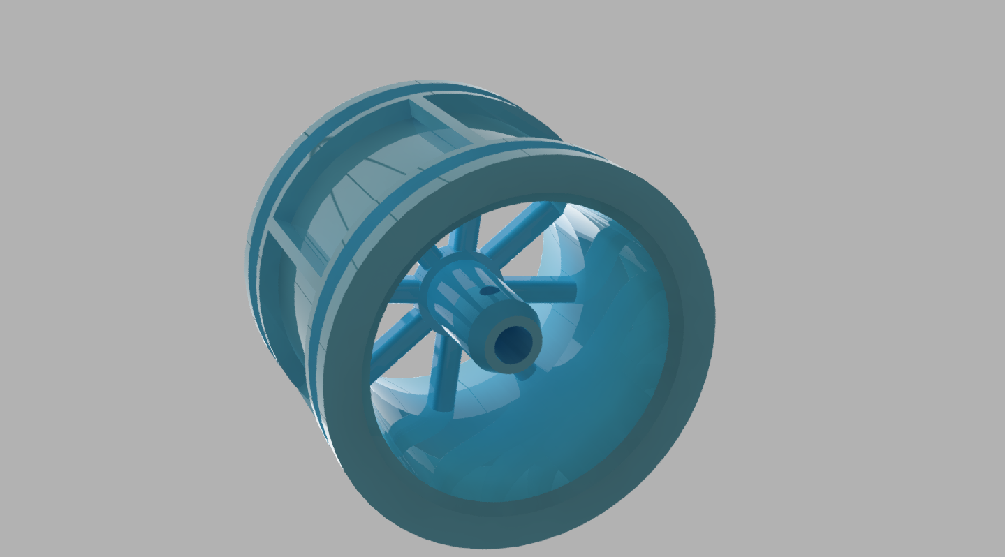
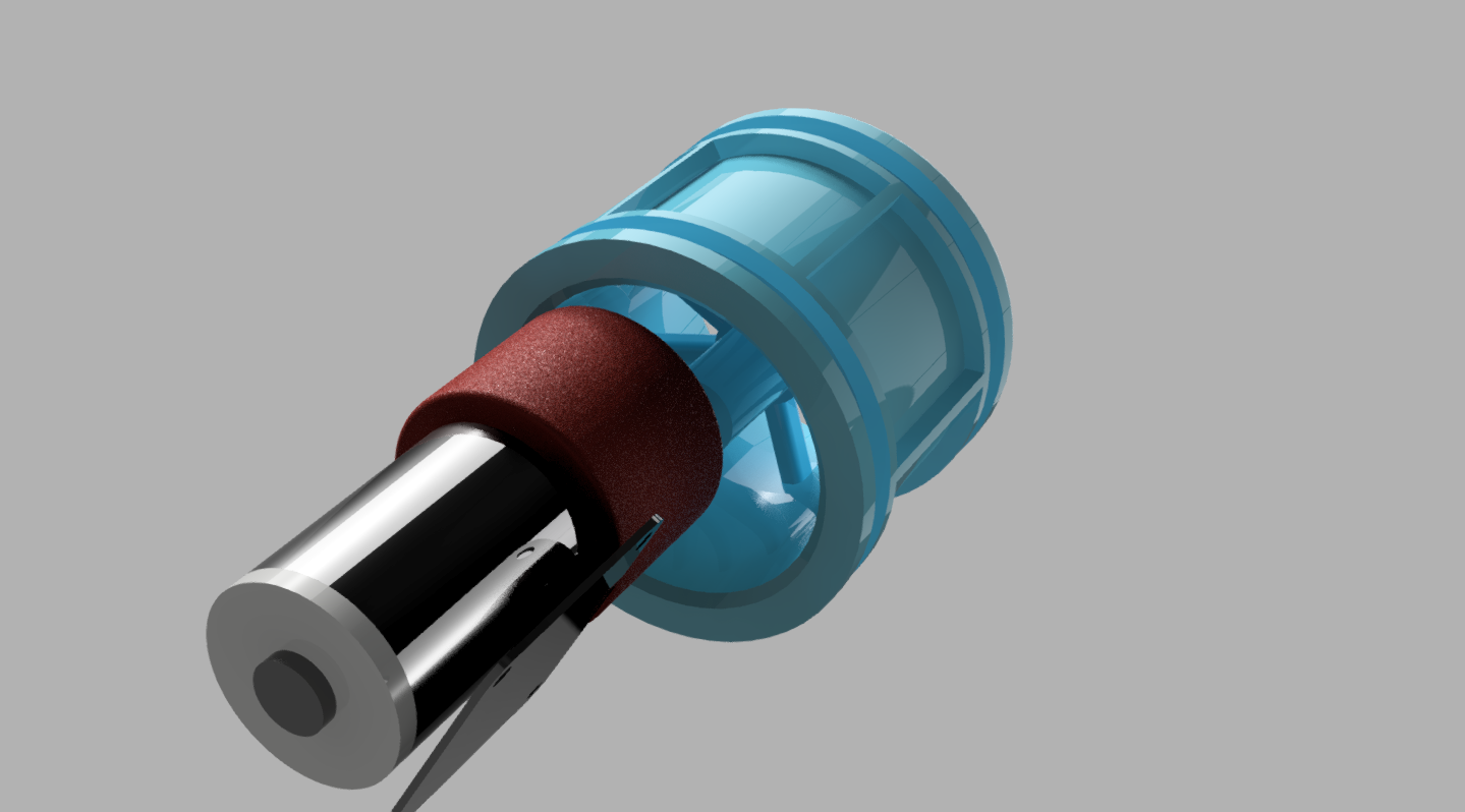
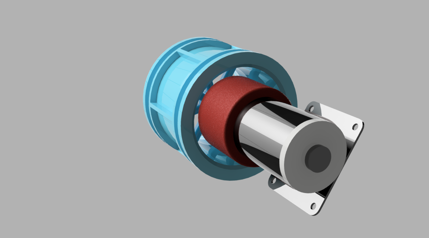
Jon is also working on the wheel encoder system, which this year we have decided to use Hall effect sensors and magnets, more on this in a later blog post.
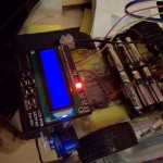
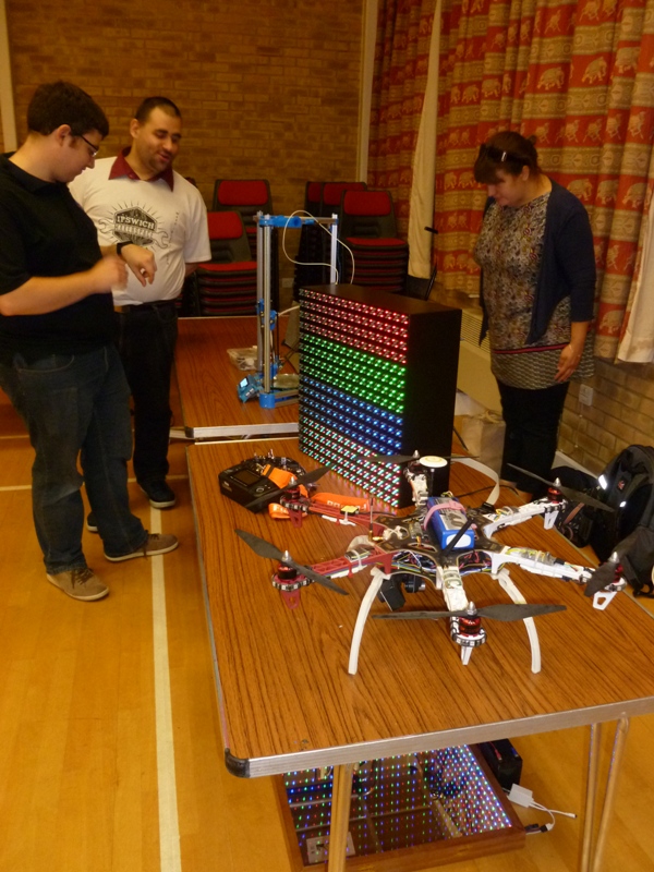
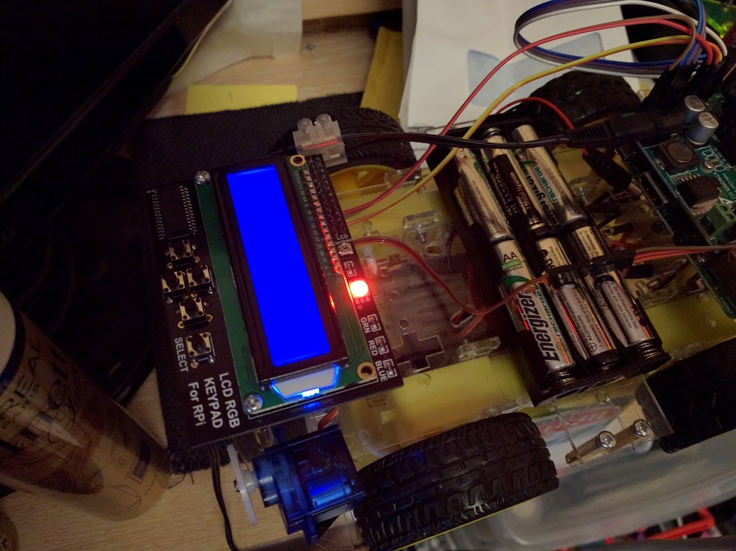
Red light – Warning, laser enabled!
Phil has also been working on the code and this was submitted for code review, although there are still some tweaks to be made. Phil also incorporated the laser guidance system in to the code.
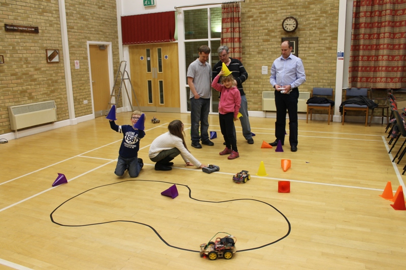
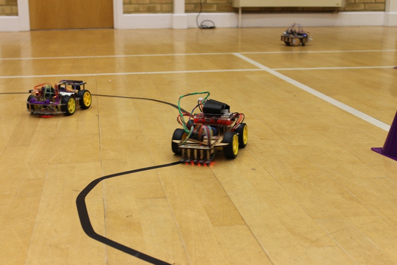
So it’s coming together and being tested on various prototypes, but it’s still a worry we don’t have a competition robot yet.
Now where did I put that time machine…