Introducing Keith Ellis, team member

Keith Ellis was at school in the age of the Sinclair ZX81 and the ZX Spectrum. He remembers getting home from school in the afternoon and setting up his dads ZX81 on a table, plugging it into the kitchen black and white TV and typing in lines of code from magazines onto the absolutely awful “touch” keyboard. He was lucky enough that his dad had also purchased 16K RAM expansion pack which upgraded it from the standard massive 1 Kilo Byte of RAM. The only issue being if you pressed the “touch” keys too hard the ram pack moved, the computer crashed and code had to be retyped from the beginning.

From this point on he was always drawn to computers, moving from the ZX81, through various versions of the ZX Spectrum, Atari ST (he remembers a day trip to Selfridges in Oxford Street with his dad to get hands on before buying), then onto Intel and AMD 386 PC’s.

When it came to choosing his GCSE subjects Keith chose Electronics as one of them, he enjoyed this lots and remembers getting the teacher to order all sorts of components to play about with, over and above the official syllabus.

Keith Ellis

Keith is the old(er) one

However on leaving school Keith decided to take a BTec in Construction and later completed a BEng (Hons) in Civil Engineering and years later has now completed many successful projects including Portcullis House in London opposite Westminster Tower (Big Ben) and more recently London Gateway Port in Essex.

Over the years Keith had kept his interest in computers, although more as a user rather than a developer, he tried several times to self teach himself programming, buying several books on programming in C, although he made progress there was never any real reason or need to develop anything so it fell onto the back burner. Later the iPhone was announced, Keith applied for a developer account, downloaded the tools and bought more books on Objective-C, but once again, there was no real need, so it fell to the back burner again.

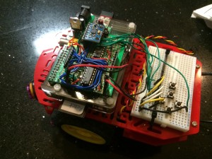
Then in April 2013 Keith ordered his first Raspberry Pi, at first he was not sure what to do with it, it was initially set it up as a media server using RaspBMC which was good, but he wanted to do more. After a bit of Googling, around November 2013, Keith decided he would build a Raspberry Pi robot. He wanted to build it from scratch and get back into electronics, so rather than buy a motor controller add on board, he bought a bread board, motor controller chip (L293D) and some wires and started messing about with LED’s, motors and Python. At last he had a project to get his teeth into and at last could progress his coding (and electronics) skills.

PiBot

PiBot just keeps growing

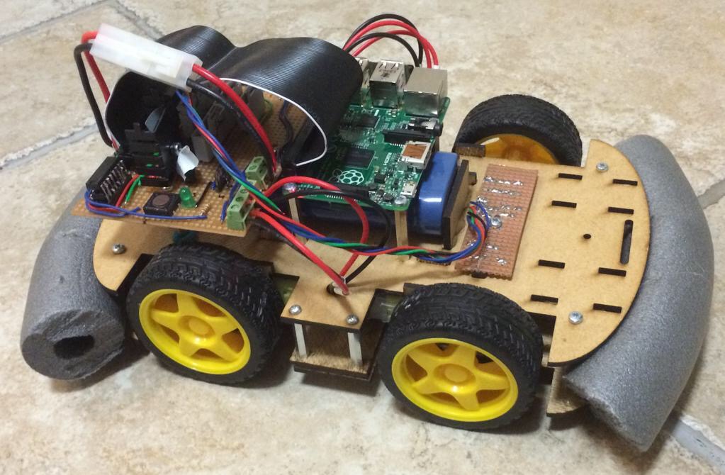
The robot is still work in progress, it now boasts a L293 motor driver, Nokia 5110 display, IR proximity sensors, MCP23008 I2C IO expander, buttons and an I2C gyro and accelerometer and bluetooth interface for Wii controller. Progress was halted on this project towards the end of last year to work on TractorBot, the Ipswich Makerspace entry for PiWars 2014. He does still continue to learn and tinker with the original robot and the LCD menu system is now operational.

Keith is very much looking forward to this years PiWars, last year was such a blast and the community spirit surrounding the event was amazing.

TractorBot 2015 is born

Last week we got lots of lovely kit from which TractorBot 2015 will be built. This week we started to put it together, albeit in a bit of a temporary way.

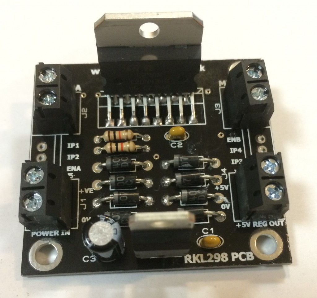
A few things need to be done, the big one is to run the motors up with wheels on so we can measure the stall current, this will then tell us the current the motor driver needs to handle. We have two motor drivers each handle 2 amps per channel, the drivers have two channels each so that gives us a total of 8 amps capacity. Keith is hoping that just one of the motor drivers will do, but until the test is complete we just don’t know.

Hub adapter

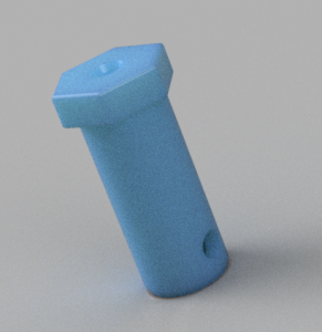
3D render of hub

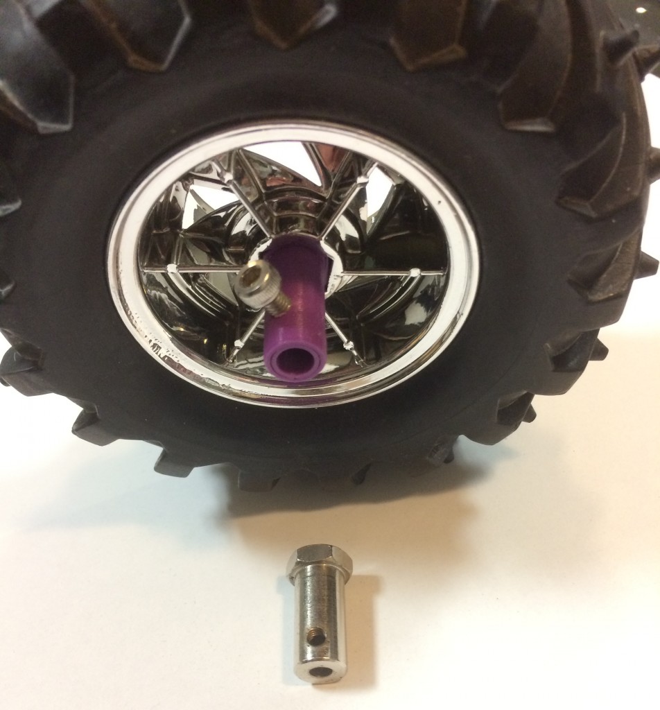
To test the stall current of the motors the wheels need to be attached, it is very difficult to stop a motor turning by holding the shaft. The only problem here is the the wheels we have came with a hub attachment for a 3mm diameter motor shaft, the motors however have a 6mm diameter shaft.

Keith quickly drew up a new hub attachment in AutoDesk Fusion 360 and Phil printed them out. The first version worked okay, good enough for prototyping anyway, so Keith attached them to the wheels ready for testing.

The new 3D printed hub attached to the wheel with the old one for comparison.

The new 3D printed hub attached to the wheel with the old one for comparison.

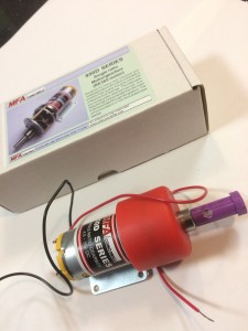
Motor with hub adapter fitted

Motor with hub adapter fitted

The new hub also fits the motor like a glove, maybe a bit too well (read, Keith cannot remove it). Now the wheels are attached to the motors, Keith will dig around in his shed to find a sheet of hardboard to use as a chassis plate. The motors will be fitted and then proper testing can commence.

One or two of these motor drivers will be required

One or two of these motor drivers will be required

Further tasks required are as follows:

  • Confirm the stall current for the motors, thus determine the number of motor driver to use
  • Fit batteries, Raspberry Pi and motor drivers to the chassis plate
  • Run some basic code, probably in Python, to check the robot moves and confirm how fast it is
  • If robot is too slow running at 7.2v, try at 14.4v
  • Design proper chassis plate

etc, etc………

So much to do.

Swag

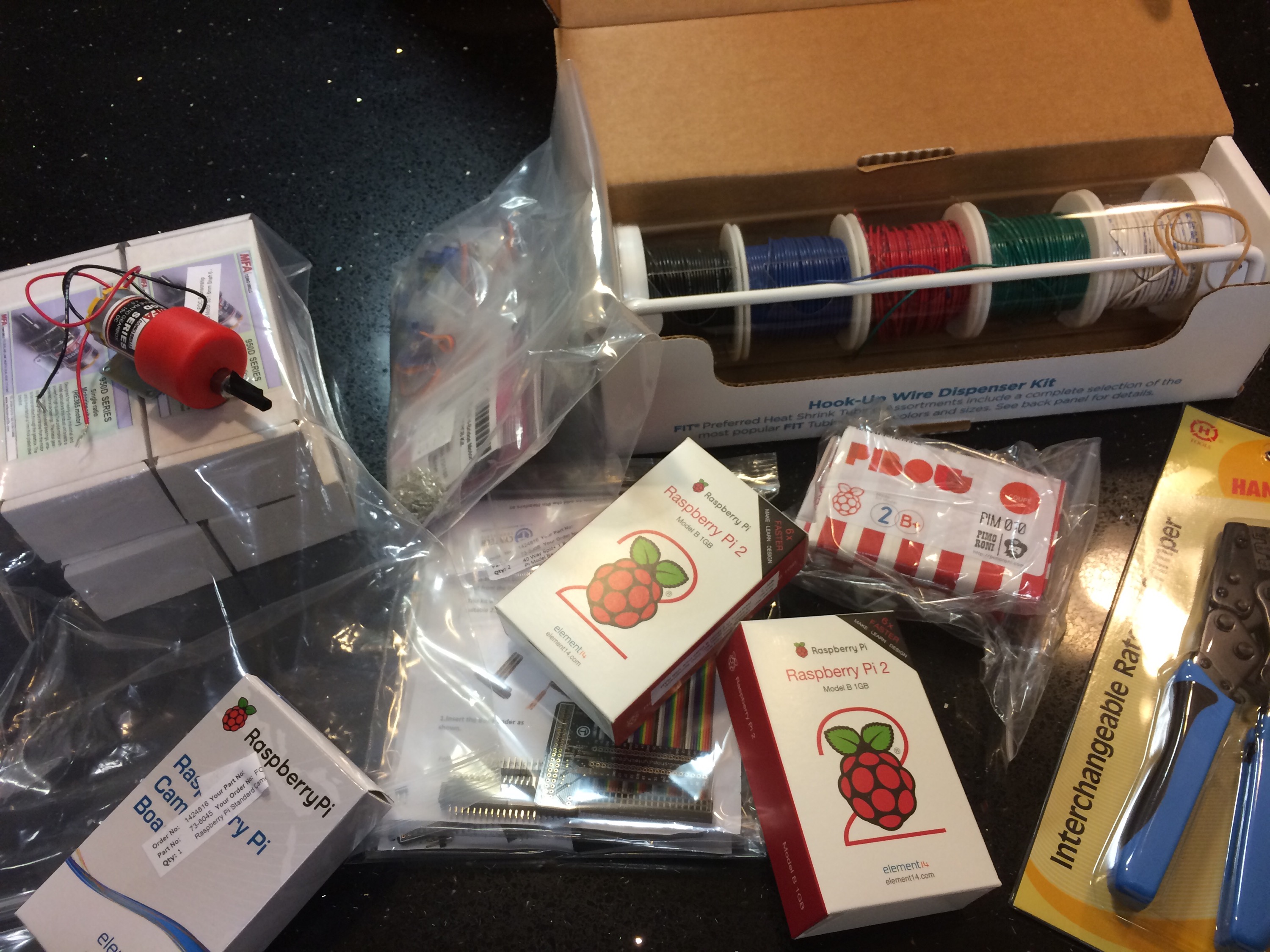
Well, we had a lovely surprise last night at the Makerspace. In the preceding week we had put a wish list together of kit for TractorBot and last night Rapid Electronics came good and a swag bag full of lovely kit was delivered.

We have Raspberry Pi’s, cases, wire, connectors, cobblers, magnets, motor drivers, motors and wheels(on back order). We are very lucky and grateful to Rapid for their generous sponsorship.

Rapid Swag

After struggling to choose the motors we were very keen to give them ago, so out came the soldering iron and soldered on a couple of wires to one of the motors. We had high expectations as we pushed the wires directly into the 7.2v battery terminals. But as the 50:1 ratio motor started to turn our excitement quickly turned to disappointment, it was slow, very slow. So this year we may well be running TractorBot at 15 volts to get a bit of extra speed.

It turns out those generic yellow robot motors are not actually that bad. 

Distance sensor

Last year we struggled with the proximity challenge a little bit. We originally chose to use an ultrasonic sensor, and to get these working, 10uS pulses are sent to the trigger pin and the time the echo pin is high is measured and converted into a distance. The Raspberry Pi is not particularly good a precise timings, it is a multi-threaded operating system and at any time it may decide to check WiFi or do some other general operating system task and miss the timings for the ultrasonic sensor. In the end we ran with an infra-red sensor which just had a high/low output with a fixed distance.

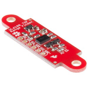
Distance sensor
This year we wanted to be able to measure the precise distance and Jon found the VL6180 infra-red sensor. This is interfaced over I2C and responds with a precise distance. This would enable the Pi to query the distance without any timing issues. The particular board we are using is from Sparkfun and it comes with information for getting started with an Arduino. Jon quickly got it up and running on an Arduino for testing and it looked very promising, so he has now produced a C library for the Raspberry Pi. You can find the library on his GitHub repository here. Jon has released the library under the MIT license so feel free to grab it and use it in your project or robot. We would love to hear if you are using this sensor or library, it looks like a very nice sensor.

I have also noticed that Leo White who is building Optimus Pi for this year’s competition is also using this sensor. He has some information on his blog here.

TractorBot 2014 Opensource update

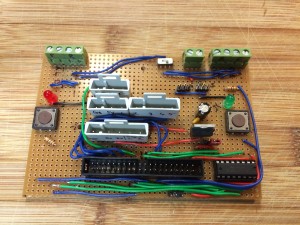
With development of TractorBot 2015 well underway for this years PiWars competition, Keith was recently looking back at last years competition. We promised to make TractorBot 2014 opensource, the lasercut files have been on GitHub for some months now, and a month or so ago, Phil added the C++ source code along with installation instructions. So last weekend Keith pushed some more commits with details of the home made motor driver and interface board along with some more descriptions on the various attachments that TractorBot was armed with.

Interfaceboard

With time marching on, our time will now be devoted to this years robot. We feel there is enough information now published on last years entry, however if you are after any specific information please get in touch, we will either update the repository or get the information over to you in some form.

All information on TractorBot 2014 can be found on GitHub here

If you use any of our resources we would love to hear about it.

Follow us on twitter @IpswMakerspace
Follow our PiWars 2015 blog ipswichmakerspace.com/piwars-2015/

Soldering tutorial

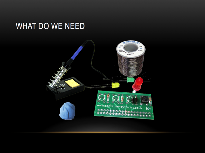
We had a great soldering tutorial at last weeks meeting, which was taken by Keith.

It consisted of a short presentation and then hands on with some Raspberry Pi kits to get some practice. It was enjoyed by all and most learnt something new and now have the confidence to get out the soldering irons and get soldering.

If you wanted to attend but could not, or even if you did attend and want a recap, the presentation is on the Makerspace wiki. Visit the wiki here:

Soldering - resized page02

TractorBot open source update

This week the TractorBot open source project took a step forward, Phil has been busy sorting out the code, it is now available on the Makerspace GitHub complete with install instructions.

Mean while Keith has been working on documenting the hardware, this is well underway but there is still a bit of work to be done.  The current work-in-progress can be seen on a branch of the GitHub repository here.

Soldering tutorial

So whilst preparing for my recent tutorial on how to use the Ryanteck Debug Clip on the Mac, I recorded myself soldering it up.

It didn’t turn out too bad so I have decided to release it as a tutorial in its own right.

Take a look, it you would like some more hands on guidance, I will be running a soldering workshop at the Makerspace on 24th September. You can view the event information here